The Toyota Production System and AI are often treated as separate domains, but in practice they are governed by the same execution principles of Quality, Standardized Work, and system responsibility.
Introduction
Artificial intelligence and humanoid robotics are entering production, logistics, and service environments faster than most organizations are prepared for. Many companies are searching for frameworks to manage this shift, but the structure they need has existed inside Toyota for nearly a century.
The Toyota Production System is the only production and management architecture already designed to separate human judgment from machine activity, expose abnormality instantly, and define work to a level that automated systems can execute.
This white paper explains why TPS is uniquely suited to a future where AI and humanoid robots perform work alongside people, and why organizations without TPS foundations will struggle to make that transition.
Purpose of This Paper
The purpose of this paper is to explain why the Toyota Production System is the only production and management architecture already structured for a future that includes AI driven automation and humanoid robots.
TPS did not emerge from automation theory or computer science. It was created to solve real production, Quality, and flow problems at Toyota. The structure that emerged from this work produced a system where machines, people, and information operate with clarity, stability, and discipline.
As AI systems and humanoid robots enter manufacturing, logistics, and service operations, most organizations are not prepared for the level of structure, stability, and abnormality management that robotic work requires. TPS is the only system that was designed from its origin to separate human judgment from machine activity, define work to a level that robots can execute, and expose abnormality in real time.
This paper outlines the elements of TPS that make it uniquely suited for this transition and explains why systems without TPS foundations will struggle to integrate robotics and AI safely, efficiently, and economically.
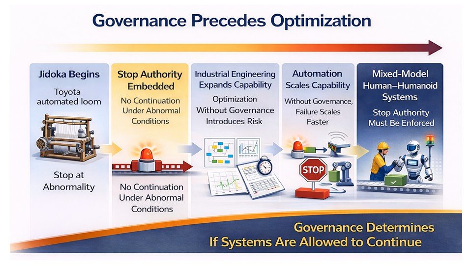
Jidoka: The First Form of Intelligent Automation
Jidoka is the original pillar of TPS. It began long before automotive production, during the development of Sakichi Toyoda’s automatic looms. The purpose of Sakichi’s invention was not efficiency or labor reduction. The purpose was Quality.
The loom was designed to stop automatically when a thread broke. This prevented the production of defective fabric. This was the first practical example of intelligent automation. The machine protected the operator and the customer by preventing defective output and signaling the need for correction.
The principles established in the loom era became the foundation for TPS:
Machines must detect abnormality
Machines must stop safely
Operators must be freed from machine watching
Human capability must be focused on problem solving, not monitoring
Quality must be built into the process and confirmed immediately
Jidoka created a clear separation between human work and machine work. A machine performs the repetitive physical task. A person provides judgment, detection, correction, and improvement.
This separation is the same requirement that AI driven automation needs today. Humanoid robots cannot operate safely or effectively in environments where work is undefined, abnormalities are hidden, and machine behavior is not connected to clear stop conditions.
TPS solved these issues a century ago.
The loom patents established a mechanical logic that still applies to AI systems:
Detect the abnormal condition
Stop the process
Signal for response
Correct the cause
Prevent recurrence
This sequence is identical to the method modern robotics engineers must use when designing autonomous systems. TPS created this logic before electronics, sensors, or software existed.
Jidoka is not historical. It is the architecture needed for intelligent automation today.
Jidoka: The First Form of Intelligent Automation
Introduction
Jidoka is the original pillar of the Toyota Production System. It began long before computer automation and shaped the early development of TPS. Jidoka was Toyota’s first method for separating human judgment from mechanical activity and making work intelligent. This principle became the basis for built-in Quality and for every form of AI-supported automation that followed.
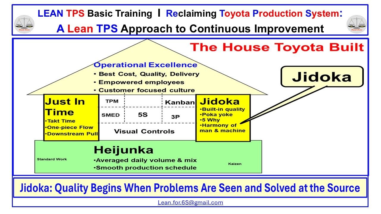
Figure 2: Jidoka as a Core Pillar of the Toyota Production System
Jidoka protects Quality by making abnormalities visible, stopping safely, and enabling structured problem solving at the source.
How Jidoka Created the First Intelligent Work System
Jidoka was the first intelligent function inside TPS. It began with built-in detection, controlled stopping, and safe correction, long before the development of digital automation. The purpose of Jidoka is to make abnormalities visible and prevent defective work from continuing. This principle shaped how Toyota designed machines, processes, and team behavior.
In TPS, Jidoka represents a system of intelligent separation between people and machines:
Machines must detect abnormality
Processes must stop safely
Leaders must respond immediately
Human capability must be focused on problem solving, not monitoring
Quality must be built into the process instead of inspected at the end
These requirements allowed machines to handle repetitive physical work while people developed judgment, discipline, and improvement capability. This was Toyota’s first model of intelligent automation: machines stabilize the work, and people strengthen the standard.
This same logic applies to AI systems, autonomous machines, and humanoid robots today:
Detect the abnormality
Stop the process
See the actual condition
Identify the cause
Improve the standard
Jidoka remains the foundation for all forms of intelligent automation. It was the first system designed to combine human judgment, machine capability, and structured problem solving into one method that protects Quality at the source.
3. Just in Time: The Blueprint for Predictable, Robot-Ready Work
Introduction
Just in Time is the second pillar of the Toyota Production System. It defines the rhythm, timing, and sequencing of work so processes can operate with stability and clarity. JIT was not created for computers or robots. It was created to remove overproduction, eliminate stagnation, and design flow that people could execute consistently.
The same structure now defines the requirements for AI-supported automation and humanoid robot work.
Figure 3: Just in Time and Jidoka Working Together in the Toyota Production System
Visual showing the interaction between Just in Time and Jidoka in stabilizing production flow and protecting built-in Quality.
How Just in Time Makes Work Executable for AI Systems
Just in Time clarifies four conditions that modern robotics and AI systems must have before they can operate safely and reliably. These same conditions were established inside TPS decades before digital automation existed.
1. JIT Defines Timing
Robots and AI systems cannot function in environments with variable cycle times, inconsistent pacing, or unpredictable waiting.
JIT establishes takt time, creating a predictable rhythm that defines:
When work starts
When work finishes
How long a process should take
This clarity eliminates the timing ambiguity that destabilizes automated systems.
2. JIT Defines Sequencing
AI and humanoid robots require precise part order, orientation, and presentation.
JIT creates this through:
Connected processes
FIFO flow
Sequenced material delivery
Removal of batching
Junjo carts, kanban sequencing, and heijunka-leveling were Toyota’s way of guaranteeing that every part arrived in the correct order.
This is the same condition required for robot execution.
3. JIT Creates Predictability
Automation cannot compensate for unstable inputs.
JIT stabilizes work by aligning production to actual customer demand and removing overproduction — the source of most instability.
Predictability enables:
Consistent workloads
Balanced work distribution
Repeatable motion
Accurate process confirmation
This stable environment is what robots depend on to perform consistently.
4. JIT Eliminates Ambiguity
AI systems fail when work is unclear, materials vary, or process definitions are incomplete.
JIT eliminates ambiguity by defining:
Exact quantities
Exact delivery points
Exact trigger signals
Exact replenishment timing
Nothing is left to interpretation.
This mirrors the requirements for autonomous systems, which must operate on defined conditions, not assumptions.
5. JIT Makes AI and Humanoid Robot Execution Possible
Just in Time defines the execution logic that allows machines and people to work together without conflict.
TPS created this logic long before robotics engineering formalized it:
Clear start and stop conditions
Stable cycle times
Sequenced materials
Defined flow paths
Visible abnormalities
Because Jidoka protects Quality and JIT defines flow, Toyota had already built the architecture needed for machine-driven work.
AI and humanoid robots are simply entering a system that was designed for structured execution from the beginning.
4. Flow: The Architecture That Makes Robotics and AI Possible
Introduction
Flow is the backbone of the Toyota Production System. It defines how work, people, machines, and materials move in a stable, repeatable sequence that exposes problems immediately. Before automation, Toyota built flow to eliminate stagnation, overproduction, and hidden abnormalities. Today, the same structure makes TPS the only system already compatible with robotics and AI execution.
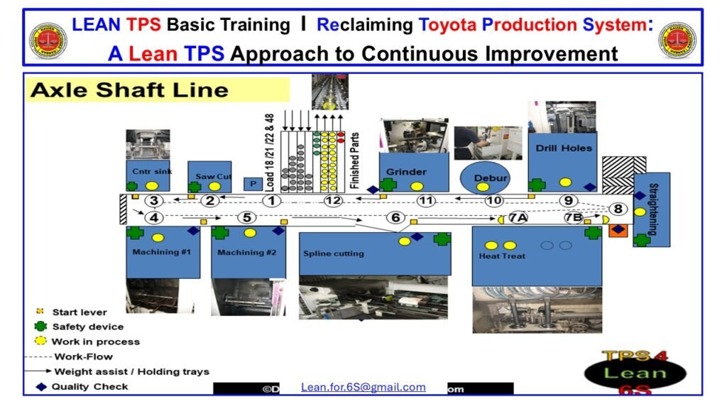
Figure 4: Axle Shaft Line Sequential Flow Layout
A real flow layout showing connected processes, FIFO lanes, and stable material movement that demonstrates how TPS creates predictable Flow.
How Flow Makes TPS Ready for Robotics and AI
Flow is not movement. Flow is the intentional sequencing of work so that every step follows the previous step without interruption, waiting, or rework. This creates the stable environment that all automated systems require.
TPS flow design enables robotics and AI execution in the following ways:
1. Flow Creates Connected Processes
Robotics and AI systems cannot operate in disconnected, batch-driven work environments.
Flow connects each step in the correct order so material moves continuously from process to process.
Connected flow ensures:
No excessive WIP buildup
No hidden waiting
No rework loops
No unpredictable transitions
This is the foundation of predictable robotic and AI movement.
2. Flow Removes Stagnation and Overproduction
Overproduction is the primary cause of instability in automation.
Flow eliminates overproduction by aligning each process to the correct timing and required work sequence.
This stability ensures:
Repeatable conditions
Predictable machine behavior
Consistent movement patterns
Robots and AI cannot compensate for unstable input. Flow removes the instability before machines arrive.
3. Flow Makes Abnormality Visible
TPS flow is designed so that any deviation from the standard immediately becomes visible.
This is essential for intelligent automation.
Flow exposes:
Delays
Missing parts
Improper sequencing
Excess motion
Safety risks
Quality problems
Robotic systems must see abnormality instantly to stop safely. TPS flow provides this visibility.
4. Flow Defines the Exact Movement of Work
Flow establishes:
The correct path
The correct direction
The correct order
The correct spacing
The correct quantity
Every automated system requires this definition.
AI and robotics cannot adapt to vague or undefined work paths. TPS flow removes the ambiguity.
5. Flow Establishes Predictable Material and Information Movement
Robotics and AI depend on predictable inbound and outbound material movement.
TPS flow ensures:
FIFO movement
Level loading
Balanced work
Consistent part presentation
Clear replenishment timing
This eliminates the uncertainty that destabilizes machine operations.
Why Flow is the Foundation for a Robot-Ready System
TPS achieved what modern automation engineers struggle with today:
Stable sequence
Continuous movement
Visibility of every abnormal condition
Defined flow paths
Controlled work-in-process
Predictable cycle patterns
Before robotics existed, TPS already created the architecture they require.
Flow makes TPS the only system designed from the beginning for safe, effective, and predictable machine-assisted work.
5. Standardized Work: The Only Method That Makes Human and Robot Work Compatible
Introduction
Standardized Work is the backbone of execution inside the Toyota Production System. It defines the best known method for performing work with stability, clarity, and repeatability. Before digital automation existed, Toyota developed Standardized Work to make human motion predictable, expose abnormalities immediately, and stabilize cycle times.
These same requirements now define the conditions under which AI systems and humanoid robots can operate safely. Without Standardized Work, robotics and automation fail because the work itself is unstable, unmeasured, and impossible to repeat.
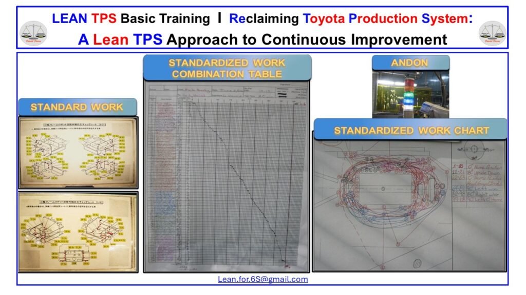
Figure 5: The Three Elements of TPS Standardized Work
The Standardized Work Sheet, Standardized Work Combination Table, and Standardized Work Chart define sequence, timing, and movement. Together they stabilize work, expose abnormalities, and create the conditions required for safe human–robot execution.
5.1 How Standardized Work Creates a Robot-Compatible Work Environment
Standardized Work establishes the only repeatable foundation that makes work reliable for both people and machines. It defines three elements that create stability in sequence, timing, and motion the three conditions AI systems and humanoid robots must have before they can operate safely.
1. Work Sequence: Exact Tasks in the Correct Order
The Standardized Work Sheet defines:
The exact steps of the job
The correct order of execution
The best known method
The conditions that indicate normal vs abnormal work
This eliminates variation in how operators perform tasks.
For robotics, this matters because AI cannot interpret inconsistent human behavior.
Robots require humans to perform work that is predictable, observable, and stable.
Standardized sequence removes guesswork and makes abnormalities visible.
2. Timing and Balance: The Foundation for Human–Robot Synchronization
The Standardized Work Combination Table defines:
Hand work time
Machine time
Walking time
Waiting time
Total cycle time relative to takt
This exposes instability such as:
Work exceeding takt
Misaligned human and machine cycles
Unbalanced workload across tasks
Excess walking that adds variability
Unstable machine interaction
Humanoid robots cannot function when cycle times shift, when operators get ahead or fall behind, or when machine time is not synchronized with human time.
The Combination Table provides the temporal stability that robotics requires.
3. Physical Motion Path: Making Human Movement Predictable
The Standardized Work Chart documents:
Walking paths
Reaches and motions
Body positioning
Interactions with parts, tools, and machines
Ergonomic risk and unnecessary motion
Robots cannot interpret ambiguous or random human movement.
They depend on humans moving in predictable trajectories, free from unnecessary travel, interruption, or unstructured motion.
The Chart provides this spatial clarity by defining the physical path of work.
5.2 Why Humanoid Robots Require Standardized Work
AI systems and humanoid robots operate on defined rules, fixed boundaries, and clear exceptions. These systems fail when:
Human motion varies
Cycle times shift
Part presentation changes
Layouts force unpredictable walking
Operators deviate from sequence
Abnormalities go undetected
Standardized Work eliminates these conditions by defining:
Exact sequence
Exact timing
Exact motion path
Visible abnormality conditions
Clear separation of human and machine tasks
Repeatable work aligned to takt time
This structure allows robots and people to work together without conflict.
Humans perform judgment-based tasks.
Robots perform repeatable, sequenced physical work.
Abnormality conditions are visible to both.
This is the environment humanoid robots require.
5.3 Standardized Work Is the Engineering of Stability
Standardized Work is not documentation.
It is the engineering of stable, predictable human work.
It creates:
Stable human motion
Repeatable cycle times
Predictable machine interaction
Clear definition of normal vs abnormal
A controlled environment suitable for robotics
Because of this, Standardized Work becomes the bridge between human capability and robotics.
AI and humanoid robots cannot compensate for unstable work.
TPS eliminates instability first then applies automation.
Standardized Work is the discipline that makes advanced automation and human–robot collaboration possible.
6. Andon: The Real-Time System That Makes Abnormality Visible
Introduction
Andon is the real-time communication system inside the Toyota Production System. It makes abnormality visible the moment it occurs. Andon separates normal from abnormal conditions, signals when support is required, and stabilizes production by triggering immediate leader response. Long before digital automation, Toyota created Andon to protect Quality, confirm flow, and prevent small problems from becoming system failures.
As AI systems and humanoid robots enter production, the need for visible abnormality increases. Autonomous systems cannot interpret unclear conditions. Andon provides the structure that defines normal conditions, signals deviation, and coordinates human and automated responses in real time.
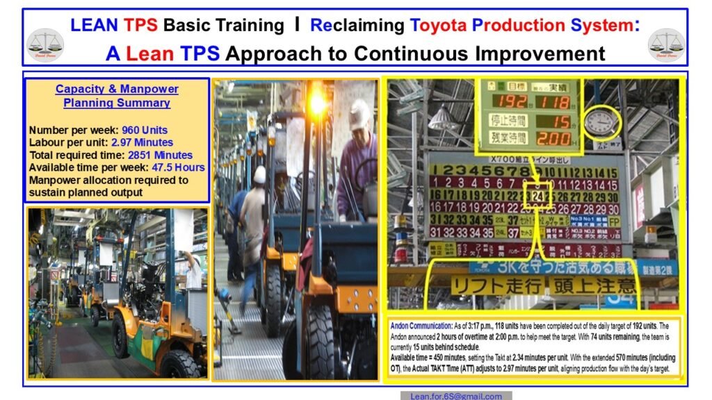
Figure 6: Andon Communication at Toyota Takahama
The Andon system displays real-time target, actual output, downtime, and remaining time. This enables immediate leader response, protects Quality, and stabilizes daily flow.
How Andon Makes Abnormality Visible and Actionable
Andon provides a real-time definition of normal conditions. When work deviates from plan, the system signals the need for support. This is not a reporting tool. It is a live control mechanism that coordinates operators and leaders.
Andon defines and visualizes four core conditions:
1. The Planned Condition
The upper portion of the board displays the daily target, expected progress by time of day, and the remaining production requirement. This establishes the standard condition of the operation.
When the planned condition is visible, abnormality becomes measurable.
2. The Actual Condition
The actual output is updated continuously. Operators and leaders can see immediately whether the line is ahead, behind, or aligned with plan.
This creates a shared understanding of flow across all levels of the organization.
3. The Abnormal Condition
When output falls behind plan, when cycle time increases, or when a defect or equipment problem occurs, Andon signals the abnormal condition through:
Light towers
Audible tones
Board indicators
Call buttons
Automatic machine stops (Jidoka)
This signal is the moment where leadership begins real problem solving.
4. The Required Response
Andon does not function without leader response. Toyota trains leaders to approach the call immediately, confirm conditions, support the operator, and contain the problem.
The purpose is not investigation.
The purpose is restoration of flow.
Why Andon Is Critical for AI and Humanoid Robot Work
Modern automation requires clarity. Autonomous systems cannot detect subtle process drift or hidden instability. Andon provides the explicit definition of normal that robots need to make correct decisions.
Andon supports AI-driven execution through:
Clear start and stop conditions
Robots require precise boundaries. Andon provides unambiguous signals that define when work should run or stop.
Real-time deviation detection
AI systems cannot assume normality. Andon exposes deviation instantly so that humans or machines can respond.
Immediate escalation
When a stop condition occurs, Andon ensures that intervention happens quickly enough to prevent downstream loss.
Stabilized flow
Robots depend on consistent cycle times. Andon prevents instability by catching drift early.
Integrated human–robot problem solving
Andon signals shape the logic that robots and humans use to respond to abnormality together.
The Andon Response Sequence That Enables Stability
Inside Toyota, every Andon call follows a consistent response cycle:
Detect abnormality
Make the signal visible
Leader arrives at the site
Confirm the actual condition
Restore flow safely
Capture the cause
Improve the standard
This cycle prevents reoccurrence and strengthens system reliability.
Andon as the Foundation for Autonomous Operations
As factories introduce AI, vision systems, and humanoid robots, Andon becomes a central architectural element. It provides:
The definition of normal
The trigger for escalation
The signal path for abnormality
The structure for human decision support
The protection for Quality when automation fails
Andon is not a display board.
It is the nervous system of TPS, providing live operational intelligence that both humans and robots require.
7. Jidoka: Stop Work When Abnormalities Occur
Introduction
Jidoka is one of the two pillars of the Toyota Production System. It is the system that ensures machines and people stop work immediately when an abnormal condition occurs. Jidoka protects Quality by preventing defects from moving to the next process. It also protects people by preventing unsafe or unstable work from continuing. The purpose of Jidoka is not to stop production. Its purpose is to stop the spread of problems and force immediate confirmation of the correct condition.
The image above shows a simple teaching visual that illustrates the core logic. If an operator continues working when abnormalities occur, defects accumulate and become invisible. When the operator stops the line and signals a problem, the abnormality becomes visible. This action allows leaders to respond, support the operator, and restore the correct condition.
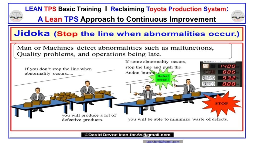
Figure 7: Jidoka visual showing how operators detect abnormalities, signal problems with Andon, and stop the line to protect Quality.
The Purpose of Jidoka
Jidoka creates a production environment where abnormalities cannot hide. The system ensures that any deviation from the expected condition results in a visible signal that demands leader response. This structure creates a learning system where problems are seen early, investigated deeply, and prevented from repeating. It also reinforces the Toyota belief that Quality is built into the process, not inspected at the end.
Jidoka is not an emergency action. It is a normal part of daily work. Operators are trained to recognize conditions that should not exist. Machines are designed to detect anomalies such as misfeeds, overloads, or incorrect dimensions. When either a person or a machine detects something abnormal, the correct action is to stop and call for assistance.
Detecting Abnormalities
The first responsibility in Jidoka is detection. Abnormalities include conditions such as:
Incorrect part placement
Unexpected machine movement
Missing components
Out of specification dimensions
Unsafe ergonomic conditions
Late process completion
Incorrect work sequence
Defects or potential defects
The operator is trained using Standardized Work to understand the correct method. This reference point makes it easy to see what is not correct. The moment the operator identifies the abnormality, they activate the Andon to call for support.
Role of Andon in Jidoka
Andon is the visual and auditory system that communicates the abnormal condition. It provides real time information to team leaders and supervisors. The purpose of Andon is to make problems impossible to ignore. It also provides a time based expectation for leader response. When the signal is activated, the team leader is required to arrive quickly, assess the situation, and either assist or authorize a line stop.
Without Andon, Jidoka becomes a private decision. With Andon, Jidoka becomes a team activity. The signal creates shared awareness and shared responsibility for restoring conditions.
Stopping to Protect Quality
Stopping the line is not a failure. It is the correct action to protect the customer and protect the system. When the operator stops the line, they prevent defects from accumulating. This makes the problem easier to identify at the source. It also forces leaders to confirm standard conditions. When the root cause is corrected, the work can continue safely and correctly.
Stopping the line also stabilizes the work for the next process. The purpose of takt time is to maintain flow at a predictable pace. Jidoka ensures that takt time is never maintained through abnormal work or hidden defects.
Leader Responsibilities in Jidoka
Leaders are responsible for responding to every Andon call. Their role is to:
Confirm the abnormal condition
Support the operator
Identify the immediate containment
Confirm whether the line should stop
Restore the correct condition
Document the abnormality
Initiate problem solving if the issue repeats
Leader response is a verification activity. It prevents work from continuing without confirmation. It also ensures that the operator does not carry the burden of abnormality alone. Jidoka is a leadership system as much as it is a Quality system.
Jidoka and AI Supported Work
As production systems move toward humanoid robots and AI supported work, Jidoka becomes even more important. AI systems require stable inputs. Robots require predictable sequences and environments. An abnormal condition makes both systems unstable. By stopping immediately when something is abnormal, the system protects both human and machine performance.
AI supported work can only function safely when the work environment is stable, repeatable, and predictable. Jidoka provides the condition that makes this possible by detecting variation at the moment it occurs and preventing it from entering subsequent processes.
Jidoka as the Foundation of Quality
Quality is not inspected at the end. Quality is created when abnormalities are prevented from flowing forward. Jidoka ensures that the system does not hide problems. It ensures that every defect is an opportunity to learn. It reinforces the belief that the operator is responsible for stopping and the leader is responsible for responding. Without this structure, defects move forward, rework increases, and learning disappears.
Jidoka protects the customer. It protects the process. It protects the operator. It creates a safe environment for stable production and efficient problem solving.
8. Pull Systems and Kanban: The Fill-Up Production System at Toyota L & F
Introduction
The Fill-Up Production System at Toyota L and F is one of the most advanced applications of Just In Time. It is not a software program or a dispatching tool. It is a physical pull system designed into the daily rhythm of machining, material handling, and assembly. The system uses Kanban, takt time, and timed replenishment loops to maintain flow without shortages, overproduction, or reaction-based logistics. Every movement of the forklift, every box of knuckles, and every replenishment interval is tied directly to actual customer demand.
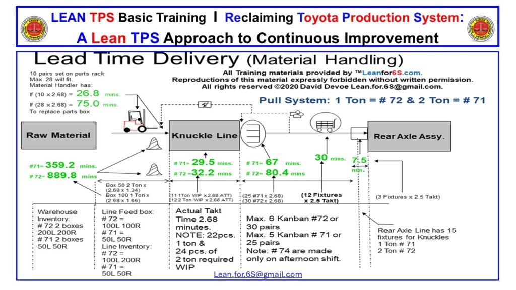
Figure 8: Toyota L and F Fill-Up Production System
Visual diagram showing the timed Kanban loops, replenishment routes, and takt-based material flow connecting the knuckle machining line, supermarket, and rear axle assembly.
A Physical Pull System Built on Timing and Consumption
The Fill-Up Production System operates as a closed-loop pull system. Consumption at the assembly line is the only signal that authorizes production and material movement. When the rear axle assembly line consumes a knuckle, that exact consumption triggers a Kanban card that moves back to the knuckle machining line. Production responds only to this physical signal. No part is produced without a card. No inventory moves without a defined pull event. This eliminates forecasting, guesswork, and safety stock.
The Role of Kanban in Controlling Work In Process
Kanban quantity defines the total controlled WIP in the system. For the 1-ton and 2-ton knuckles, Toyota uses strict Kanban limits that reflect real replenishment needs. The 1-ton knuckle uses five Kanban cards, and the 2-ton knuckle uses six. These limits prevent overproduction by establishing a physical upper boundary for inventory. When all cards are in process or in transit, production cannot continue. Kanban becomes the governing mechanism for both stability and timing.
Replenishment Timing Designed from Actual Takt Time
The Fill-Up System is built on the takt of the rear axle assembly line. The takt time of 2.68 minutes defines how quickly knuckles must be consumed and therefore how often material must be replenished. The system calculates replenishment loops directly from this takt time. For example, replenishing ten pairs of knuckles requires 26.8 minutes, and replenishing twenty eight pairs requires seventy five minutes. These times include distance, loading, layout, and box capacity. Material handling becomes a timed function, not a reactive one.
Material Handling as Part of the Value Stream
In many factories, forklifts react to shortages and deliver material only when operators call for help. Toyota designs material handling as an active part of the value stream. The forklift operator follows a timed route that matches assembly consumption. Each loop is defined by distance, load size, cycle time, and Kanban quantity. When the forklift moves, it is participating in a synchronized flow system. Material handling becomes predictable and repeatable, supporting Just In Time rather than responding to emergencies.
Integration Between Machining, Supermarket, and Assembly
The Fill-Up System links the knuckle machining line, the supermarket, and the rear axle assembly line through a shared timing structure. Machining produces knuckles based on card return. The supermarket holds measured inventory based on card quantity. The assembly line consumes in line with takt. This three-way connection stabilizes flow. When assembly uses a part, the supermarket initiates a replacement through Kanban. Machining responds. Material handling executes the timed route. This structure ensures that all three processes operate as a unified system.
Visibility and Immediate Abnormality Detection
The visual diagram shows that every loop, time interval, and route is designed to reveal abnormalities immediately. When a route takes longer than expected, the timing gaps become visible. When a Kanban card does not return, the signal chain is broken. When consumption patterns change, Kanban quantity becomes misaligned with takt. These abnormalities are detected as soon as they occur because the system is built on timing, not judgment. Leaders respond early, preventing shortages and overproduction.
Inventory as a Function of System Design
Measured WIP in the Fill-Up System is the result of timing and Kanban limits. The system does not rely on safety stock. The 1-ton knuckle operates with an active WIP of twenty two pieces, and the 2-ton knuckle operates with twenty four. These quantities emerge directly from replenishment intervals, box size, and distance. Inventory levels are not policy decisions. They are engineered outcomes of a synchronized pull system.
Why This System Represents True Just In Time
The Fill-Up Production System demonstrates that Just In Time is not scheduling software. It is a physical design that aligns human work, material handling, and machine processing into a rhythmic pattern. Production, replenishment, and logistics operate from a shared takt. Abnormal conditions become visible through delays in timing or breaks in the Kanban loop. This structure allows Toyota to sustain high-mix operations with stability and Quality. It prevents chaos by ensuring that the system itself reveals and controls variation.
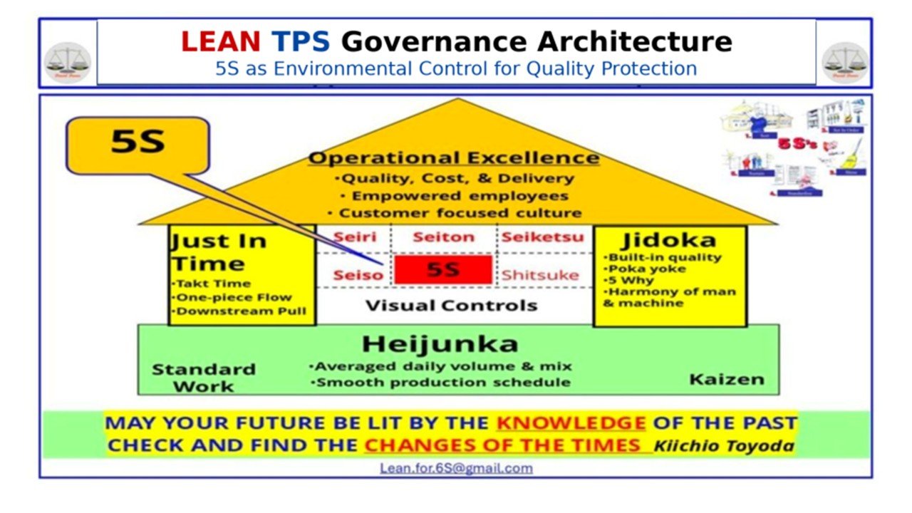
9. Level Loading and Heijunka: The System Foundation Designed for Humanoid Robotics
Introduction
TPS treats Level Loading and Heijunka as core structural requirements for stability, flow, and Quality. These methods remove day-to-day variation in production quantity and model mix, allowing people, machines, and supporting processes to operate at a consistent rhythm. This stability is why Toyota can sustain high-mix production without volatility. It is also what makes TPS designed for humanoid robotics. Humanoid robots cannot adapt to unstable demand, inconsistent sequences, or unpredictable workloads. Heijunka and Level Loading remove the instability at the planning stage so the execution environment remains stable for both people and robots.
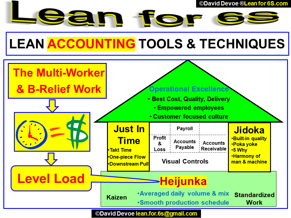
Figure 9: Lean Accounting Tools and Techniques
Lean Accounting visual showing how Just in Time, Jidoka, Heijunka, Level Load, and Standardized Work support operational excellence inside structured TPS systems.
Why Unleveled Work Prevents Humanoid Robots from Operating Safely
Unleveled work introduces instability at the foundation of an operation. When daily quantity or model mix fluctuates, the system experiences overload on some days and underload on others. This instability forces operators to:
change sequences
vary pace
run overtime
work through shortages
rely on emergency material handling
adjust conditions without confirmation
Humanoid robots cannot function in this environment. Their programs depend on predictable pacing, stable sequences, and consistent presentations of parts and tools. When the plan oscillates, robots face conditions outside their design envelope. Variability in human pacing, machine cycles, or model mix increases the risk of misalignment, stoppage, or Quality loss. The problem is not the robot. The problem is the plan. TPS prevents this instability with Level Loading and Heijunka.
How Level Loading Creates the Baseline Rhythm of Work
Level Loading establishes a daily production rate that the system can execute consistently. This removes the spikes and valleys in workload that normally drive firefighting. Level Loading defines:
the expected daily output
the allocation of work by hour and shift
the quantity each process must produce
the material replenishment pattern
the supporting manpower structure
This stable rhythm prevents variation from reaching operators and machines. It also prevents hidden variation from entering Standardized Work. Humanoid robots depend on this rhythm because they cannot adjust to unplanned increases in takt, fluctuating workloads, or irregular sequence changes. Level Loading guarantees that takt remains stable and predictable across the planning horizon.
Heijunka Distributes Model Mix Predictably Across the System
High mix is normal inside Toyota. The Heijunka Box distributes this model mix in small, predictable intervals rather than in long batches. This reduces setup variation, stabilizes workload, and protects Standardized Work from disruption. Heijunka ensures:
consistent sequence of models
balanced use of fixtures
predictable material presentation
stable timing for upstream machining
clear signals for material handling
even load on supporting resources
For humanoid robots, this is essential. Robots require stable sequencing to avoid unexpected changeovers or task variations. A sudden shift from one model to another introduces changes in motion, path, or part orientation that must be validated. Heijunka removes these surprises by spreading model mix evenly so every hour of work reflects the expected pattern.
How the Lean Accounting Structure in the Visual Supports Stability
The Lean Accounting house graphic shows how JIT, Jidoka, Heijunka, and Standardized Work support Operational Excellence. Level Load sits at the foundation because it determines the pace at which all other functions operate. This structure illustrates several TPS truths that apply directly to humanoid robotics:
JIT cannot function without Level Loading
Jidoka cannot protect Quality when work is unstable
Standardized Work cannot hold when mix or pace fluctuates
Material handling cannot synchronize without stable timing
Humanoid robots cannot execute work that varies from shift to shift
The Lean Accounting view reinforces that stability is not a financial concept. Stability is an operational requirement that affects every part of the production system.
Why Level Loading and Heijunka Are Required for Humanoid Robotics
Humanoid robots replicate human-scale tasks, walking paths, reaches, and tool handling. To perform these tasks safely and accurately, they require:
fixed takt time
stable sequence
predictable presentation
repeatable workloads
clear boundaries between normal and abnormal
Level Loading provides the fixed daily rhythm. Heijunka provides the stable mix and sequence. Together they form the architecture of work that humanoid robots need.
Without Level Loading:
takt fluctuates
cycle time shifts
support patterns break
operators and robots get out of sync
Without Heijunka:
model mix changes unpredictably
sequences become unstable
material arrives in inconsistent orientations
robots cannot execute defined tasks safely
Both methods must be present before humanoid robots are introduced. TPS already provides these conditions by design.
How Level Loading and Heijunka Protect Quality in Mixed Human–Robot Work
Quality risk increases when humans and robots share the same space but operate under unstable conditions. Level Loading and Heijunka reduce this risk by:
eliminating hidden variation
stabilizing Standardized Work
synchronizing human and robot cycles
ensuring material arrives in specific, repeatable formats
protecting downstream processes from fluctuation
Humanoid robots require environments where normal conditions are clearly defined and repeatable. Heijunka and Level Loading create this environment so Jidoka and Andon can protect Quality when abnormalities occur.
Why These Methods Make TPS the Only System Designed for Humanoid Robotics
Modern automation leaders often try to adapt their operations by adding software, dashboards, and forecasting tools. These methods cannot replace the structural logic of TPS. TPS is the only system where:
flow is stable
pacing is defined
mix is leveled
sequence is predictable
abnormalities are visible
Quality is protected
work is standardized
support is immediate
machines and people operate with shared takt
Humanoid robots require these conditions. TPS already provides them. Level Loading and Heijunka make TPS designed for humanoid robotics before robotics existed.
10. Takt Time: Designing the Rhythm That Humans and Humanoid Robots Must Share
Introduction
Takt time defines the pace of production inside the Toyota Production System. It is the mathematical relationship between customer demand and available operating time. This single calculation establishes the required rhythm for every process in the system. Takt time does not describe how long work takes. It defines the pace at which work must be completed so that flow remains stable, inventory remains controlled, and human and robotic work remain synchronized. In an environment that includes humanoid robots, takt time becomes even more critical. Robots cannot adapt to unstable pacing, inconsistent sequencing, or unpredictable workloads. They require a fixed, repeatable rhythm. Takt time provides that rhythm.
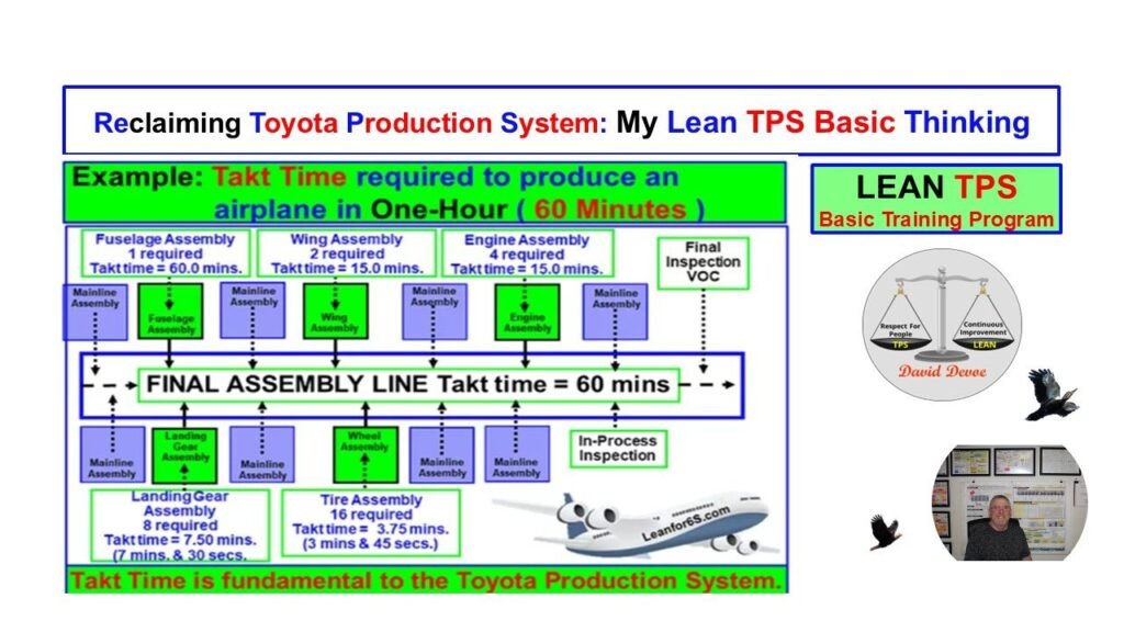
Figure 10: Lean TPS Takt Time Airplane Example
Takt time training example showing how all upstream processes must align to a 60-minute final assembly takt to sustain stable flow.
How Takt Time Creates the Rhythm Required for Humanoid Robotics
Takt time is a calculation, not an estimate. It defines the exact interval at which the final assembly process must produce each unit in order to meet customer need. Every upstream process must align to this interval. When takt time is calculated correctly, the entire system operates with a stable rhythm. Workflows become predictable, abnormalities stand out immediately, and both people and humanoid robots can operate within known timing boundaries. When takt time is calculated incorrectly or ignored, instability enters the system. Processes speed up and slow down unpredictably, inventory fluctuates, and abnormalities are hidden. These conditions prevent both human operators and humanoid robots from working safely and effectively.
The airplane example illustrates the principle. Final assembly must produce one unit every sixty minutes. This takt time becomes the reference condition for every supporting process. Sub-assembly processes must produce the correct quantity of components within the same sixty-minute window. If the final assembly takt is sixty minutes and a supporting process must deliver two units within that window, its required pace becomes thirty minutes per unit. If another process must deliver four units within the same window, its required pace becomes fifteen minutes per unit. This alignment is the core of takt-based system design. Every process must operate at a mathematically correct rate relative to the final assembly takt.
This requirement creates the stability that humanoid robots depend on. Robots cannot compensate when processes fall behind takt, exceed takt, or shift pacing throughout the day. They require a stable interval for every work cycle. When takt is correct, robots can repeat their programmed movements with precision. When takt is incorrect or unstable, robots are forced into conditions outside their design limits. This creates Quality risk, safety risk, and flow disruptions that no automation system can resolve.
Takt time also stabilizes human work. Operators can maintain consistent motion patterns when pacing is predictable. When takt remains fixed, Standardized Work can be designed to match the correct rhythm. Walking paths, work sequences, and machine interactions become consistent and measurable. This stability strengthens human capability and supports humanoid robot integration. Both humans and robots require the same condition: a defined, repeatable pace of work.
Takt time exposes abnormalities immediately. Any deviation from the expected output within the takt interval becomes visible. If a single workstation consistently exceeds takt, the system cannot maintain flow. If a process produces earlier or later than takt allows, the imbalance becomes visible through waiting, overproduction, or inventory accumulation. These visible conditions support Jidoka, Andon, and problem-solving activity. When abnormality is visible, leaders can respond before the issue spreads.
Humanoid robots amplify this requirement. When robots operate at a fixed pace and human processes are unstable, the difference becomes visible almost immediately. Robots will reach their cycle completion point on time, even if upstream work is delayed. This creates gaps, waiting, or shortages. Likewise, if upstream work exceeds takt, robots may not be able to accept the additional output. Takt time is the bridge that ensures robots remain synchronized with human work and with the flow of materials across the system.
Takt time is not a planning tool. It is the foundation of execution. It ensures that human work and humanoid robotic work operate within the same rhythm. It aligns every process to the customer. It exposes abnormality at the moment it occurs. When takt time is calculated correctly and followed consistently, the production system gains the stability required for advanced automation. When takt is unstable, the system becomes unpredictable and unsafe for both humans and robots. TPS established this structure decades before humanoid robotics existed. It remains the core condition that makes TPS designed for humanoid robotics today.
11. Multi-Process Work: How Toyota Designs Human Motion for Stability, Quality, and Robotics
Introduction
Multi-process work is one of Toyota’s most advanced forms of Standardized Work. It is used when one operator supports several stations in sequence, maintaining flow on a moving assembly line. This method requires precise definition of motion, timing, and confirmation points. Without this structure, human work becomes unpredictable, abnormalities remain hidden, and automation cannot operate safely.
The Type II Standardized Work chart from Toyota L&F Takahama Plant Line 2 shows the walking paths, work steps, cycle times, and interactions across four stations. This visual demonstrates the discipline behind Toyota’s method for designing human activity with the same precision applied to machines. This structure is the foundation required before introducing humanoid robots into shared production environments.
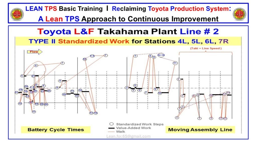
Figure 11: Multi-Process Standardized Work at Toyota L&F Takahama
Type II Standardized Work for Stations 4L, 5L, 6L, and 7R showing operator walking paths, work elements, and cycle alignment with line speed.
Why Multi-Process Work Defines the Human–Machine Interface
Multi-process work is used when operators must support more than one process in sequence. Unlike single-station work, multi-process operations expose every weakness in layout, flow, sequence, and motion. Toyota developed Type II Standardized Work to stabilize these conditions by defining the exact path operators travel, the time required at each station, the order of work elements, and the expected relationship between manual work and machine time.
The chart shows four key features:
• Structured movement
• Defined value-added work
• Precise walking paths
• Cycle alignment with line speed
These features ensure that work is predictable, visible, and synchronized with takt. This is the precision that humanoid robots require in order to operate safely alongside people.
Multi-process work stabilizes system rhythm by eliminating the ambiguity that causes variation. When one operator supports multiple stations, even one second of deviation becomes visible at the next process. This forces structure into the design. Every step, reach, and confirmation point must be engineered. The walking path cannot be arbitrary. Timing cannot drift. Sequence cannot change from cycle to cycle. This is not documentation. It is system design.
Toyota applies this same logic when designing robots. Human motion must be predictable so that automation can be integrated safely. A robot cannot interpret inconsistent walking patterns or changing work sequences. Multi-process charts like this one expose those patterns and remove variation before automation is considered.
At Takahama, the operator supports four adjacent stations on a moving line. The line does not wait for an operator who is behind. For this reason, the walking path is drawn against takt. The red lines show walking motion. The black lines show value-added steps. The numbered circles define each work element. The horizontal axis represents time against line speed. The vertical spacing represents location on the moving line.
This makes two conditions immediately visible:
• Whether the operator is ahead or behind relative to takt
• Whether station interaction is stable or unstable
Any abnormality appears as a break in the expected pattern. This visibility allows leaders to respond quickly and prevents instability from reaching customers.
Multi-process work also clarifies machine interaction. Operators must load, unload, inspect, and confirm work at each station. Machines must perform their portion of the work within a defined window. If either human or machine drifts, the next station is affected immediately. This is why multi-process work is the best representation of the TPS human–machine interface.
Humanoid robots also require clear separation between human movement and machine activity. The Type II chart creates this separation by engineering the operator path and defining the boundary between manual and automated work. The visual shows where machines operate independently and where the operator must interact. This prevents overlap, collision, and confusion.
The stability created by this structure enables predictable cycle times. Cycle drift is one of the main causes of automation failure. When human work varies, robots attempt to adjust, often creating unsafe or unstable conditions. Multi-process Standardized Work removes this drift by clarifying the correct movement, timing, and sequence.
This method also clarifies leadership behavior. Team leaders at Takahama use these charts during audits, training, and problem solving. When abnormal conditions occur, the leader can refer to the chart to confirm whether the operator or the station deviated from the standard. This creates a learning environment where improvement is based on facts, not opinion.
Multi-process work remains one of the most advanced forms of TPS because it combines flow, timing, motion, sequence, and confirmation into one visual. It is not simply a tool for efficiency. It is a method for creating stability that protects Quality and enables safe, predictable integration of AI systems and humanoid robots.
When multi-process Standardized Work is in place, automation does not enter chaos. It enters a designed, stable system where human and machine work in alignment with takt. This makes multi-process work a key element of any future production system that includes humanoid robotics.
Building Control Through Information and Flow
Introduction
This section explains how Lean TPS creates stability by designing the movement of information as deliberately as the movement of material. Without clear information flow, no production system can achieve rhythm, Quality, or predictability. This chart illustrates how TPS exposes hidden complexity, restructures decision pathways, removes approval delays, and converts chaotic administrative work into a controlled process that supports flow at the shop floor and office levels.
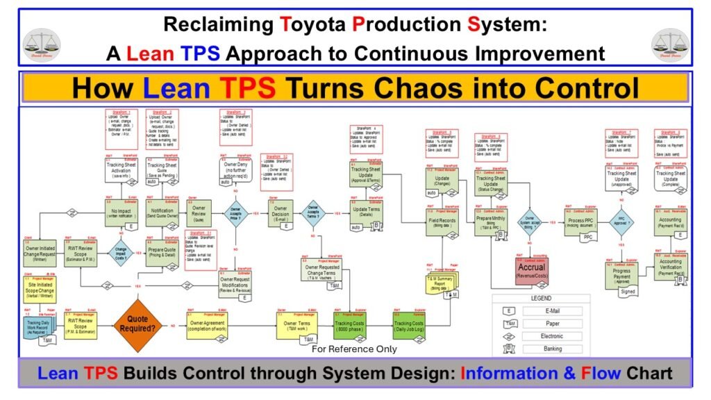
Figure 12. Information and Flow Chart for TPS System Design
This chart shows the complete administrative and transactional flow, highlighting decision paths, approvals, and information movement required to stabilize the process.
How Information Flow Determines System Stability
Lean TPS recognizes that information flow defines system behavior. When information is unclear, delayed, duplicated, or inconsistently routed, the entire organization absorbs the instability. Operators wait. Leaders expedite. Work piles up in hidden queues. Quality decisions are made without complete facts. These failures are not caused by people; they are caused by system design. The purpose of TPS is to engineer a flow of information that supports Quality at the source and enables every process to operate with predictable timing.
Information flow governs lead time. Before improving any work sequence, TPS clarifies who makes decisions, what inputs they require, and how information moves from one step to the next. This prevents the common failure mode in traditional organizations where problems arise from incomplete or unclear instructions, missing approvals, or inconsistent communication paths. By visualizing the full administrative pathway, TPS reveals how much variability originates upstream of the physical work being performed.
A system can only be stable if information arrives at the right time. The chart illustrates how Lean TPS exposes the difference between an uncontrolled process and a structured system. Each shape, arrow, and decision point identifies a specific movement of data, authorization, or confirmation. When these paths accumulate without design, the organization experiences rework loops and firefighting. TPS eliminates this condition by engineering information flow that supports takt, capacity, and Quality requirements.
Decision points represent major sources of delay. Approvals, exceptions, and clarifications create queues that disrupt timing. TPS reduces these points by clarifying standards, defining normal conditions, and removing approval requirements that do not protect Quality. The fewer decision gates a process contains, the more predictable the flow becomes. This aligns directly with the Toyota principle that unnecessary variation in information is a form of waste equal to unnecessary movement in material.
The design of information flow is a leadership responsibility. Leaders ensure that every person in the process understands what information they need, where it comes from, and when it must be available. This supports judgement that is both informed and timely. A well-designed information system reduces ambiguity and prevents the formation of hidden work. It creates conditions where associates can focus on executing value-added work rather than searching, waiting, or guessing.
TPS uses visual system design to make the invisible visible. Many administrative or transactional processes appear simple at first glance, yet once mapped, they reveal long chains of email, approvals, revisions, and handoffs. These pathways form the “chaos” that Lean TPS must convert into control. Through visualization, teams can identify unnecessary checks, unclear responsibilities, and inconsistent communication loops. Each of these represents a failure point that adds cost and reduces Quality. By eliminating or consolidating them, TPS reduces lead time significantly.
Stable information flow supports stable material flow. Production timing cannot be managed if upstream processes do not supply instructions, confirmations, and prioritization signals at the correct interval. This is why TPS integrates information and material flow into a single system. Both must move with rhythm and clarity. When information flow is corrected, the physical work becomes easier to stabilize. Processes experience fewer interruptions, and production schedules become achievable.
The transformation from chaos to control begins with recognizing that information paths require the same engineering rigor as equipment layout, walking patterns, and standardized work. TPS treats information as a component of the system, not an administrative afterthought. Redesigning information flow aligns the entire organization around a clear sequence of activities and decision logic. This is the foundation for predictable performance and sustainable improvement.
TPS builds systems that prevent failure rather than reacting to it. By engineering information flow, leaders remove uncertainty from daily work and create an environment where associates can deliver Quality consistently. The chart demonstrates how a complex process becomes manageable when mapped, clarified, and simplified. This is how Lean TPS builds control, protects Quality, and ensures flow across both production and administrative environments.
Section 13 — Standardized Work Combination Table
Introduction
The Standardized Work Combination Table is the primary TPS tool for understanding the interaction of manual time, walking time, and machine time within a production cycle. It provides the factual basis for determining whether the operator’s work aligns with takt time and whether the sequence supports stability, flow, and built-in Quality.
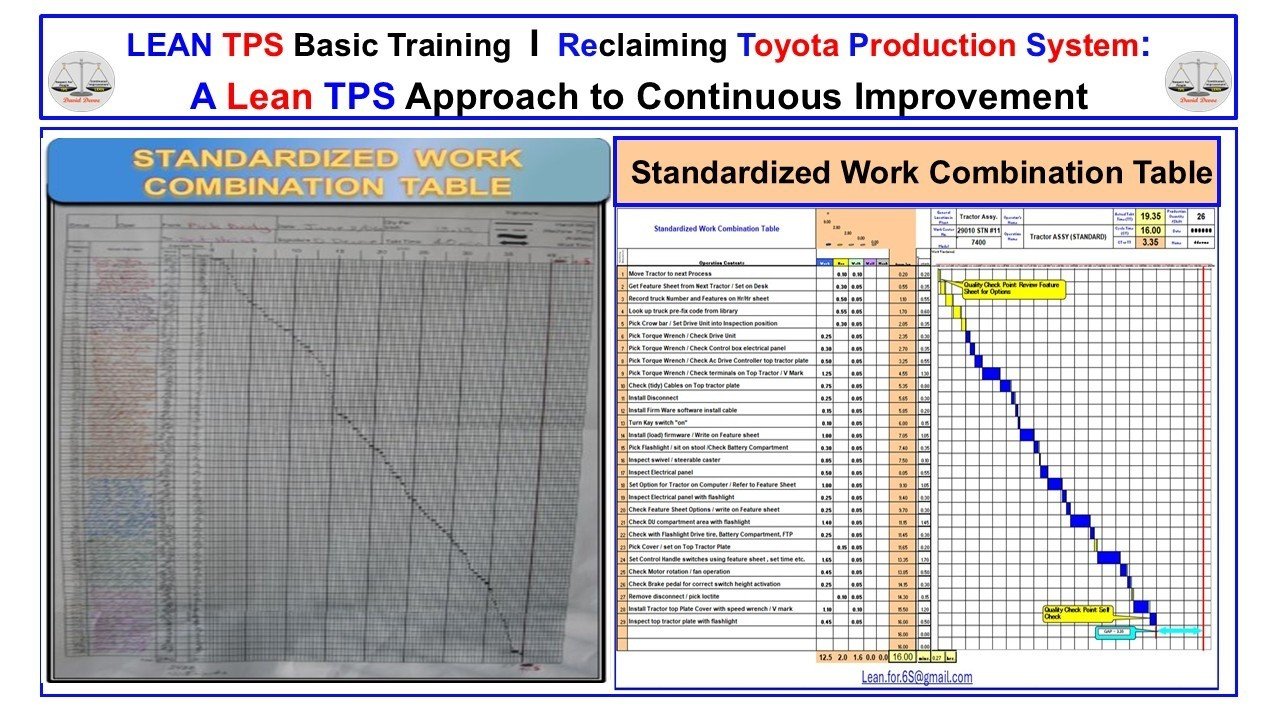
Figure 13A Caption:
Hand-drawn SWCT used to teach element breakdown, sequence, and manual confirmation before software tools are introduced.
Figure 13B Caption:
Completed digital SWCT with element times and a time-line chart confirming alignment to takt time.
Understanding Time, Sequence, and Flow in Standardized Work
The Standardized Work Combination Table represents the technical foundation of operator-level work control inside the Toyota Production System. It combines all three elements of Standardized Work: the takt time of the process, the fixed sequence of work elements, and the standard in-process stock required to maintain uninterrupted flow. By plotting each element against a time scale, the table makes Quality, stability, and motion problems visible.
The hand-drawn version on the left reflects Toyota’s training approach. All team members learn Standardized Work using paper and pencil because the method forces close observation and accurate recording of each element in real time. Writing the elements by hand strengthens the ability to see motion, classify work, and recognize the difference between value-added and non-value-added activity. Before software is introduced, the operator must understand the thinking behind the table.
The digital version on the right presents the same information in a structured SWCT format. Each element is assigned manual time, walk time, or machine time, and the time-line chart confirms whether the sequence fits within takt and whether the workload can be balanced across operators. The shape of the curve exposes unevenness, inconsistency, or unnecessary walking. It also highlights Quality confirmation points and areas where cycle time exceeds takt.
This tool is essential for line balance and stability. If any element changes, the table must be updated to maintain control over the sequence and to prevent the introduction of variation. Because the SWCT shows the interaction between walking and manual work, it becomes the first place where leaders investigate abnormal motion, missing elements, or increases in cycle time. It also helps identify opportunities for kaizen by isolating unnecessary steps or excessive movement.
The strength of the Standardized Work Combination Table is its precision. When built correctly, it provides a clear picture of how the operator performs the work, how the sequence supports flow, and where improvements can be made without compromising Quality. The discipline of maintaining the table is part of Toyota’s leadership system. It ensures that Standardized Work remains the baseline for improvement and that changes reflect actual work conditions on the shop floor.
14. Information and Flow Map for Final Assembly
Introduction
The Information and Flow Map defines how work, materials, and information move through a complete assembly line. It is the system-level view of Standardized Work, showing how individual work elements connect across stations to create stable flow, balanced workload, and built-in Quality.
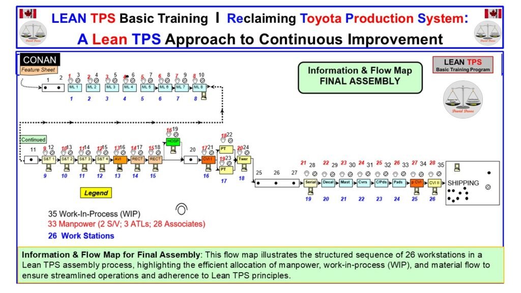
Figure 14. Information and Flow Map – Final Assembly
System-level flow map showing the complete 26-station final assembly sequence, including information triggers, material movement, manpower allocation, and work-in-process required to maintain flow.
Information and Flow Control in a Lean TPS Assembly Line
The Information and Flow Map is the foundation for designing and improving an assembly line. It converts customer demand and takt requirements into a structured sequence of stations, material routes, information signals, and manpower distribution. Unlike generic process maps, this TPS method integrates material and information flow into one view, showing exactly how the system must function to maintain stability and built-in Quality.
This final assembly map defines 26 workstations arranged in a continuous one-direction flow from feature sheet input to shipping. Each station corresponds to a Standardized Work Combination Table and a defined element sequence. The structure ensures that all work aligns to takt and that in-process inventory is controlled intentionally. This prevents hidden queues and avoids local optimization that would undermine system performance.
The early section of the line shows model-line feeders that must supply components in takt to prevent shortages and line interruption. Their placement on the map makes upstream dependencies visible, reinforcing the principle that flow must be designed and not left to chance. The transitions through fabrication, assembly, inspection, and testing show exactly where Quality confirmation occurs. These support steps are positioned at the point of risk so abnormalities surface immediately.
Work-in-process is limited to 35 units across 26 stations. This level reflects the physical demands of the line, the work content, the takt rate, and the required buffer to maintain stability during minor disturbances. Maintaining this WIP level exposes abnormalities in real time rather than allowing inventory to hide them.
The manpower structure is also defined. Thirty-three team members support the line, including team leaders and assistant team leaders positioned where variation and Quality risk are highest. This aligns with the TPS principle that leaders must be located where problems occur, not in remote offices or removed from the flow.
The Information and Flow Map must be updated whenever takt, sequence, model mix, or work content changes. It prevents improvement activity from drifting away from system requirements and ensures that Standardized Work remains synchronized across stations. When maintained correctly, it provides the visibility required to improve the entire system, not isolated processes.
15. Carriage Assembly: 5W2H Problem Solving at the Source
Introduction
This section uses the Carriage Assembly Information and Flow Chart to show how Toyota integrates 5W2H problem solving directly into the work. Quality at the source is not a slogan. It is a design requirement built into flow, layout, information triggers, and operator roles. The chart shows how the workstation structure, material routing, and confirmation points form a learning system that identifies and responds to abnormalities immediately. This same structure supports AI and humanoid robots by stabilizing the inputs, clarifying expectations, and exposing any deviation from normal conditions.
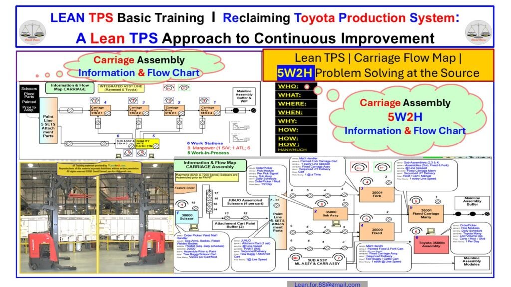
Figure 15: Carriage Assembly 5W2H Information and Flow Chart
Carriage Assembly Information and Flow Chart showing how 5W2H problem solving is built directly into the flow to detect abnormalities at the source and protect quality.
Understanding Structured Problem Solving Inside the Flow
Quality at the source in Toyota systems is achieved by building problem identification into every part of the process flow. The Carriage Assembly Information and Flow Chart shows how workstations, material routing, confirmation points, and operator movement create an environment where abnormalities cannot hide. Instead of separate audits or after-the-fact inspection, the flow itself becomes the mechanism for detecting deviations. The use of 5W2H reinforces this by giving each team a simple, structured question set that clarifies the problem before any countermeasures are considered.
The chart illustrates how each workstation is connected through a defined sequence of material and information events. Operators receive parts, instructions, and reference sheets in a consistent order. Sub-assemblies feed into specific stations, and each arrival point has a confirmation requirement. These confirmations are not optional. They are embedded into the Standardized Work so that operators must interact with them. This prevents silent failures and ensures that every carriages’ build conditions are checked at the correct time and location.
The 5W2H block inside the graphic reinforces one of the core principles of TPS: problems must be understood at the exact point where they occur. The questions—Who, What, Where, When, Why, How, and How Many—ensure that the team clarifies facts before discussing solutions. This prevents assumptions and reduces the risk of countermeasures that address symptoms instead of causes. Because the 5W2H format is simple and repeatable, it can be applied within seconds at the workstation without interrupting the line.
The lower section of the chart includes the integrated sub-assembly flow, forklift routing, and material staging designed to support the line at takt. Each path shows how carts, sub-assemblies, fixtures, and painted components arrive in the correct order and quantity. When any part of the route deviates—such as delays, shortages, incorrect model selection, or an abnormal material presentation—the structure exposes the condition immediately. This early visibility allows leaders to respond before the abnormality becomes a defect.
The photos of the Raymond scissors reinforce another element of TPS: observation is the basis of learning. Although software captures data and supports planning, operators and leaders rely first on physical confirmation. The machines, layout, flow lanes, and material positions tell the actual story of performance. This is the environment that AI and humanoid robots must operate in. These systems require clear, consistent inputs. They cannot compensate for poor process structure or unclear information flow.
The Carriage Assembly Chart demonstrates how TPS creates a stable baseline for both people and machines. Each station has a defined task set, each confirmation occurs at the same physical point, and the overall flow makes abnormalities visible. When a robot or AI agent is added, it interacts with a structured, predictable pattern rather than a variable, reactive environment. The 5W2H framework also supports AI by producing consistent problem data that can be interpreted without ambiguity.
The strength of this chart is that it combines flow, control, quality, and learning into a single visual representation. It shows that improvement is not a project. It is a system of interdependent elements: Standardized Work, information flow, point-of-cause confirmation, material routes, visual control, and structured problem solving. Together, these elements ensure that quality is produced through design, not inspection, and that humans and automation can operate within the same stable rhythm.
Type I Standardized Work: One-Piece-Flow in a Low-Volume, High-Mix Assembly Line
Introduction
Type I Standardized Work represents the purest expression of one-piece-flow. In low-volume, high-mix environments, this form of standardized work removes inventory buffers, exposes abnormalities immediately, and forces every station to operate in alignment with takt time. This section uses a 13-station tractor assembly line to illustrate how Lean TPS designs flow, stabilizes sequence, and creates Quality at the Source through standardized motion, clear flags, and controlled movement conditions.
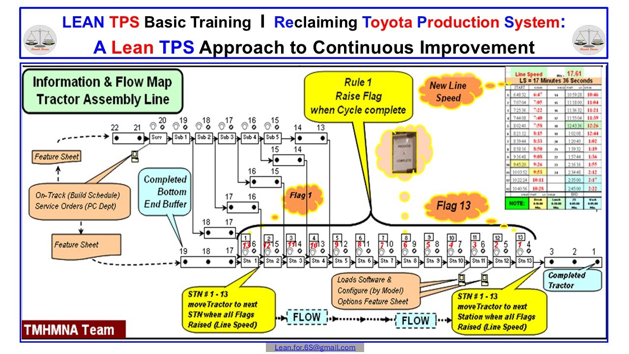
Figure 16: Type I One-Piece-Flow Assembly Line
One-piece-flow across 13 stations using Type I Standardized Work to control sequence, timing, and movement through a raise-flag cycle completion system.
One-Piece-Flow as the Foundation of Stability and Quality
One-piece-flow is the highest level of flow design because it eliminates the buffers and batching that hide unstable work conditions. In a Type I Standardized Work environment, the movement of each unit is synchronized strictly to takt time, and every station depends on the completion of the prior station before work can begin. The 13-station tractor assembly line shown in Figure 16 illustrates how Lean TPS structures this flow and maintains stability in a low-volume, high-mix environment.
The first design principle is that movement only occurs when every station completes its cycle. This is controlled visually through the raise-flag system. Flag 1 indicates that the upstream station has delivered a completed cycle. When all flags across the 13 stations are raised, the line advances one position. This movement rule prevents early releases, protects downstream work conditions, and reinforces the discipline required for one-piece-flow. Because no station can hide behind accumulation, abnormalities surface immediately. Any delay, missing part, or incorrect cycle time becomes visible and forces a leadership response.
The second principle is the elimination of intermediate inventory. In the map, there are no buffers between the 13 stations. Work-in-process is restricted to the single unit at each station, plus a small completed-tractors buffer at the end. This design ensures that each associate must complete work within takt time and that any deviation from standard sequence is exposed. It also stabilizes material handling, because parts arrive exactly when required for the current cycle. This reduces floor congestion and allows part kitting to be synchronized directly with assembly.
The third principle is the clarity of work sequence. Type I Standardized Work requires that each element be documented, validated, and timed. Associates follow a fixed sequence that matches the layout and tool locations. The visual map displays each step, sub-process, and quality checkpoint in the order required to complete the tractor. Because the sequence is standardized, any deviation becomes a signal for analysis rather than random variation. This supports both quality assurance and training, ensuring that new associates can reach stability quickly.
The fourth principle is the design of Quality at the Source. Quality gates are placed where defects are most likely to occur. These checkpoints are incorporated into the standardized sequence and cannot be bypassed. Each gate is tied to takt time and aligned with the raise-flag system so that defects are captured before the unit moves forward. The design forces the team to correct issues in real time rather than passing them downstream. This creates a learning environment in which teams understand the causes of variation and continuously improve their work methods.
Finally, the one-piece-flow line integrates line speed control. The right side of the map shows the line-speed chart, which compares actual cycle time to the takt requirement. By visualizing the gap, leaders can adjust manpower, reassign tasks, or conduct kaizen to close performance gaps. This ensures that the line maintains flow without overburdening associates or allowing instability to accumulate.
Type I Standardized Work is more demanding than Type II or Type III methods because it exposes instability immediately. This is why it is the foundation for mature Lean TPS systems. When properly designed, it delivers predictable flow, stable work conditions, higher Quality at the Source, and a disciplined team culture capable of sustaining continuous improvement.
Section 17. Type II Standardized Work in a High-Mix Moving Assembly Line
Introduction
Type II Standardized Work is the core method for stabilizing high-mix, small-lot production in a moving assembly environment. At Toyota Logistics and Forklifts in Takahama, this method is used to synchronize manpower, work content, and line speed so every model variation can be produced with consistent Quality. This section shows how flow, staffing, and takt alignment are maintained even when dozens of tractor and forklift models run on the same line.
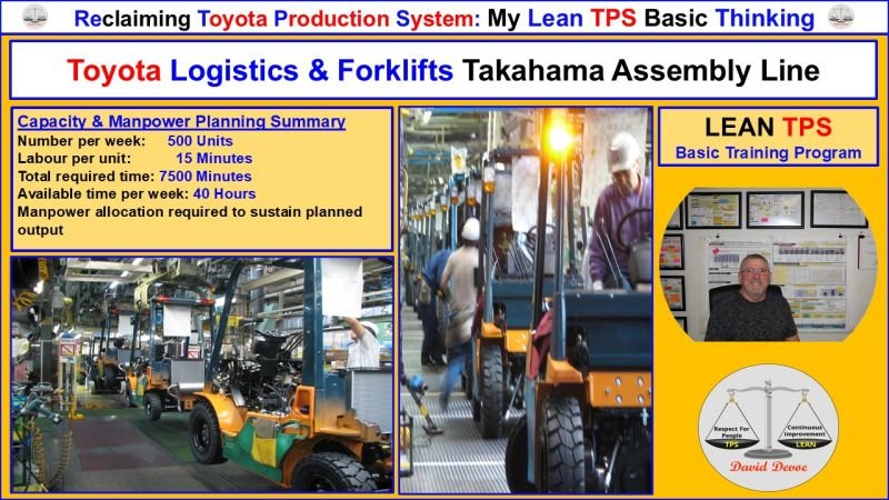
Figure 17. Type II Standardized Work in a High-Mix Moving Assembly Line
Type II Standardized Work applied on the Toyota L&F Takahama assembly line, showing mixed-model flow, operator staffing, and the capacity and manpower summary required to maintain line speed.
Understanding Type II Standardized Work in High-Mix Assembly
Type II Standardized Work is designed for flow lines where products move continuously and operators must complete work within a fixed travel distance and time. Unlike Type I, which is suited to stationary or bench-style assembly, Type II must integrate walking time, reach patterns, component variation, and model sequencing into one coherent system. The stability of the line depends on how well manpower is assigned against takt time and how much work content variability exists between models.
In Takahama, this approach is essential because a single line may produce 1-ton to 10-ton forklifts, tow tractors, sweepers, and specialized variants. Each model has a different assembly load, but the line speed does not change. Standardized Work must therefore identify the true manual work time, the walking paths, and the machine or automatic time for each element, ensuring operators remain balanced to takt.
Capacity and manpower planning is a critical part of this system. Required minutes per unit are converted against available time to determine the exact staffing required to maintain stable output. If labour allocation falls below the requirement, line speed cannot be sustained. If it exceeds requirements, waste is built into the system. Type II Standardized Work prevents both conditions by linking manpower decisions directly to takt time.
The image illustrates three key principles:
Flow must never stop. Operators complete their work as the tractor or forklift advances through each work zone.
Manpower must match takt. The system calculates total minutes required per week and aligns staffing to maintain the planned output.
High-mix conditions require strict element confirmation. Every element must be verified for consistency, regardless of model variation.
This approach provides the mechanical stability needed for Kaizen. Once flow and manpower are established, abnormalities such as delays, reach patterns, missing parts, or ergonomic issues become visible. This visibility is what allows the Takahama line to maintain high Quality and support continuous improvement in a mixed-model environment.
Section 18. Operator Activity Chart
Introduction
The Operator Activity Chart is a critical tool inside the Toyota Production System. It visualizes the relationship between manual work, walking time, waiting time, and machine time for each operator in a shared process. This chart exposes imbalance, highlights waste, and reveals opportunities to redesign work so each operator supports line stability and takt adherence. By making operator time visible in a structured format, leaders can verify whether work sequences support flow and Quality, and whether the process design prevents overburden.
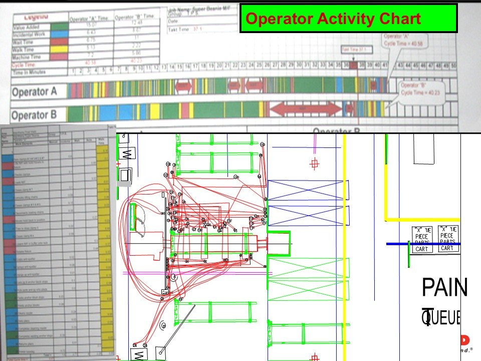
Figure 18. Operator Activity Chart
Operator Activity Chart illustrating operator timing, walking, and work sequence alignment relative to takt.
Analyzing Work Balance Through Operator Activity
The Operator Activity Chart is one of the three foundational documents in Standardized Work. It serves a different purpose than the Work Combination Table or the Standardized Work Chart. Where those documents define timing and sequence, the Operator Activity Chart exposes the physical reality of how operators move and interact with their environment.
This chart separates time into clear categories: manual work, walking, machine time, and waiting. By displaying each category along a timeline, the chart makes uneven work distribution immediately visible. When two operators support the same process, differences in cycle lengths, timing overlap, or delays caused by walking become clear. This visibility is essential for identifying the root causes of missed takt, instability, or recurring line delays.
The chart also makes movement visible. Excessive walking, long travel paths, repeated loops, or cross-traffic become evident when the walking lines are superimposed over the layout. This is where the Operator Activity Chart contributes directly to waste elimination. Once movement is visualized, layouts, material presentation, and work elements can be redesigned to support shorter paths, better sequencing, and reduced burden. This ensures that each operator can complete their work safely, consistently, and within takt.
During Jishuken, this chart becomes the anchor for coaching. Leaders use it to verify that operators understand their sequence and that workloads are balanced. When differences appear between planned and actual work, the chart helps determine whether the issue is training, layout design, or missing Standardized Work conditions. It also serves as a communication tool, allowing teams to agree on improvement priorities based on facts rather than assumptions.
The Operator Activity Chart strengthens the connection between people, process design, and system performance. By exposing imbalance and unnecessary movement, it supports Quality at the source, reinforces proper work sequence, and builds a stable foundation for further kaizen. It ensures that Standardized Work is not a document but a lived practice based on real observation and real conditions on the floor.
Section 19. Jishuken: Mid-Term A3 for System-Level Improvement
Introduction
The mid-term A3 is the central document used in Jishuken to connect daily operational problems to structured, system-level improvement. It provides a disciplined way to define the background, understand the current condition, quantify the gap, and clarify the actions required to close it. Unlike short-term problem solving, the mid-term A3 aligns leadership, team capability, and system design. It ensures that improvement work is driven by facts, verified at the gemba, and executed through a sequence that protects flow and Quality.
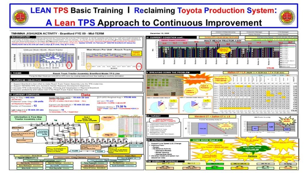
Figure 19. Jishuken Mid-Term A3
Mid-term A3 used in Jishuken to clarify background, current condition, target, and strategy for structured improvement.
Clarifying System Problems Through Mid-Term A3 Thinking
The mid-term A3 is the anchor of Jishuken activity. It provides a structured, visual method for understanding the system as it actually operates, not as leaders assume it operates. The document begins with a clear background statement that explains why the topic is important. This prevents teams from launching improvement work without a defined purpose. The background establishes context, identifies the problem area, and connects the improvement to broader organizational requirements.
Next, the A3 presents the current condition. This section is built from direct observation rather than second-hand reports or historical data. Leaders and team members visit the gemba to gather facts, confirm actual work sequences, and understand the conditions that operators face each day. The current condition must be documented precisely because it becomes the reference point for all improvement decisions. Without a clear and accurate understanding of the present state, improvement activity risks drifting toward opinion or preference.
The gap analysis quantifies the difference between the current condition and the desired future state. This gap is expressed through measurable indicators such as productivity, flow stability, Quality performance, or workload distribution. The purpose of the gap analysis is not to create a list of problems. It is to identify the core obstacles preventing the system from meeting its targets. These obstacles become the focus of the improvement strategy.
The target condition defines the measurable results the team must achieve. In Jishuken, targets are established based on capability and necessity, not aspiration. Targets must reflect what the system needs to function correctly, whether it is takt adherence, reduced defects, balanced workloads, or shorter lead times. The target condition is a statement of performance that can be verified through observation and measurement.
The strategy section outlines how the team will close the gap. This includes the sequence of actions, expected outcomes, required training, and resource needs. The strategy is not a list of ideas. It is a structured plan that integrates Standardized Work, flow design, material movement, and leader development. Each action must contribute directly to achieving the target condition. The strategy also identifies the specific leaders responsible for each action, reinforcing accountability and alignment.
The schedule section defines the timeline for implementing and verifying improvements. Jishuken requires that improvement be confirmed at the gemba through real-time observation. The schedule includes milestones, review checkpoints, and follow-up dates. This ensures that improvements do not fade and that leadership remains engaged throughout the cycle.
The mid-term A3 reflects the purpose of Jishuken: to develop leaders through hands-on improvement work and to strengthen the system through disciplined problem solving. It transforms improvement from a project into a structured process based on observing actual conditions, clarifying gaps, and executing targeted actions. The A3 format provides the structure that enables teams to see problems clearly, respond effectively, and sustain the gains made during the Jishuken event.
20. Final Jishuken Example: System Stability Before Automation
Introduction
This final section demonstrates how a complete Jishuken A3 validates system stability before any consideration of robotics, AI, or humanoid automation. The A3 below represents full-system TPS problem solving based on direct observation, fact-based analysis, and structured kaizen. It shows how line balance, Quality conditions, manpower loading, and flow must be stabilized to support predictable performance.
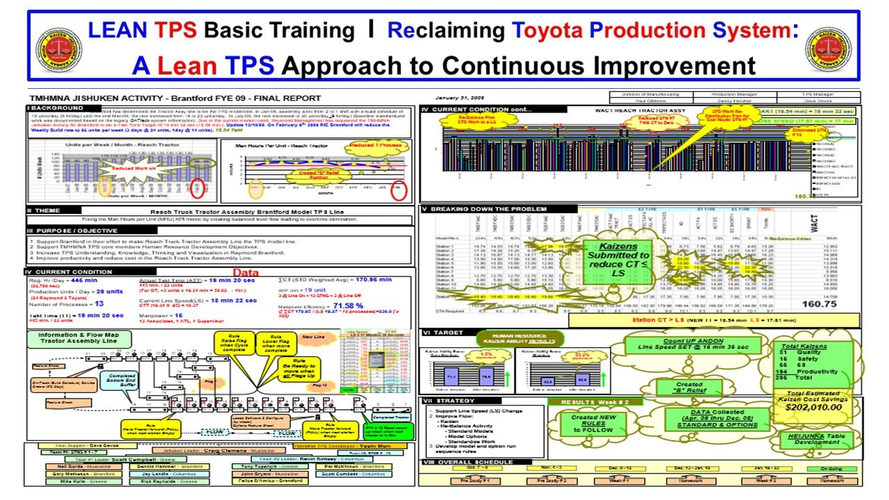
Figure 20. Final Jishuken A3: Full-System TPS Analysis and Stabilization
Full Jishuken A3 summarizing system flow redesign, cycle-time imbalance, manpower loading, and targeted kaizen actions required to stabilize the assembly line.
Why System Stability Is the Prerequisite for Robotics and AI
The Jishuken A3 shown here highlights the level of system clarity required before any advanced automation can be considered. It documents a complete evaluation of the reach-truck assembly line, including true cycle-time behavior, manpower allocation, workstation imbalance, and flow disruption. Each data set is confirmed through observation at the point of work, never through assumption.
The A3 reveals core contributors to instability: variation in work sequence, inconsistent material presentation, missing parts, and operator overburden. By mapping the real condition, the team identifies the gaps between the designed Standardized Work and what is actually occurring on the shop floor.
Targets are set using takt time and required operating conditions. The A3 shows how uncontrolled variation in cycle time spreads unevenness across downstream stations, increasing strain and reducing Quality. Kaizen actions focus on stabilizing manual work, sequencing tasks correctly, improving part presentation, and reducing wasteful movement.
The “breaking down the problem” section demonstrates Toyota’s discipline: isolating the specific flow obstacles, confirming them with operators, and redesigning the process to eliminate root causes. Once imbalance is reduced, the line begins to operate predictably, and Quality improves because upstream instability no longer cascades into defects or rework.
This Jishuken example reinforces the central message of the white paper: automation amplifies the system it enters. If instability exists, robots and AI amplify instability. If the system is stable, technology amplifies performance. Therefore, system stability must be achieved first through TPS fundamentals—Standardized Work, level loading, clear flow, visual control, and direct observation.
Only after these foundations are verified can automation and AI support the process without introducing risk.
Closing: Preparing Your System for AI and Humanoid Robots
This whitepaper demonstrated that advanced automation does not create stability. It depends on it.
AI systems, autonomous equipment, and humanoid robots require conditions that most organizations do not currently have: defined work, predictable timing, controlled flow, structured problem response, visible abnormality, and stable interfaces between machines and people. These conditions are not created by software, sensors, or robotics. They are created by the Toyota Production System.
Each element in this paper: Jidoka, Just in Time, Flow, Standardized Work, Andon, Kanban, Heijunka, and Jishuken exists to remove ambiguity, expose abnormality, and stabilize the rhythm of work. Together, they form a complete architecture that makes both human and machine performance predictable. This is why Toyota could integrate automation safely decades before most companies understood the requirements. TPS is a system designed for a world where human judgment and machine activity must operate side by side without conflict.
As leaders consider AI and humanoid robots, several questions become unavoidable:
Is your work sequence defined clearly enough for a robot to execute?
Can your operators, machines, and material flow maintain takt without fluctuation?
Do you have real-time visibility of abnormality, or do problems hide inside the noise of daily variation?
Does your organization rely on firefighting, or are problems surfaced immediately and solved structurally?
Are your current processes capable of supporting automation, or would robots magnify the instability that already exists?
These are not technical questions. They are system questions.
And they reveal whether a factory is prepared for advanced automation—or whether automation will expose weaknesses that TPS was designed to prevent.
If your organization is preparing for AI, autonomous systems, or humanoid robots, the first requirement is not technology. It is a stable TPS foundation. Without the structure outlined in this whitepaper, automation will struggle, performance will degrade, and Quality will suffer. With the correct TPS conditions in place, automation becomes an extension of flow, not a disruption to it.
If you want support designing or rebuilding the TPS structures needed to create predictable, robot-compatible performance, I work directly with leaders to implement these methods in real operations. The purpose is simple: establish the system conditions that allow people, processes, and machines to operate with clarity, stability, and Quality.