Module 3 — Standardized Work: The House Toyota Built
Section 1 — Introduction to Standardized Work
Standardized Work is the foundation of stability, flow, quality, and improvement inside the Toyota Production System.
This page introduces how Standardized Work integrates with Just In Time, Jidoka, and Heijunka, forming the base of the TPS House.
This version is written for you to study the work sequence, takt time, and SWIP connections inside real Toyota operations.
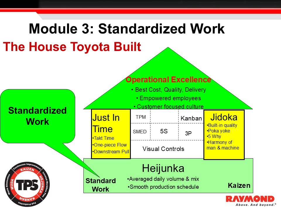
Figure 1. The House Toyota Built:
Standardized Work supports Just In Time, Jidoka, and Heijunka to create operational excellence.
Purpose of Standardized Work
Standardized Work creates the baseline that supports stability, flow, quality, and leadership development.
Inside Toyota, Standardized Work is not a document. It is a method for defining the safest, most efficient, and most repeatable way to perform work at a given moment.
This method provides the basis for confirming abnormalities and for improving the process.
Instructor Explanation
Standardized Work is a core method within the Toyota Production System.
It links directly to the three pillars of the TPS House:
Just In Time — requires predictable timing and flow
Jidoka — requires abnormalities to be visible
Heijunka — requires stable workloads and repeatability
Without Standardized Work:
flow cannot stabilize
takt time cannot be applied
abnormalities cannot be seen
kaizen becomes random
quality and safety variation increases
Standardized Work is built on three elements:
Takt Time — the pace required to meet customer demand
Standardized Work Sequence — the repeatable order in which work is performed
Standard Work In Process (SWIP) — the minimum material needed to maintain flow
When these three elements are clear, leaders and operators can:
observe real work accurately
detect variation
confirm abnormalities
improve the process using kaizen
protect flow and quality
Heijunka supports Standardized Work by leveling the workload. When volume fluctuates, the work cannot stabilize. Leveling demand allows operators to perform tasks at a consistent pace with reduced burden and fewer interruptions.
Standardized Work is revised only when an improvement is verified.
Each revision becomes the new baseline.
This ensures improvements remain stable and the system does not drift from TPS principles.
Visual Reference
Slide: Module 3 – Standardized Work, The House Toyota Built
Purpose: Demonstrates how Standardized Work forms the base of the TPS House and supports JIT, Jidoka, and Heijunka.
Instructor Notes
Standardized Work is a method, not paperwork
Stability must be built before takt and sequence can be applied
Abnormalities become visible only when the standard is clear
Kaizen requires a baseline
Agenda & Learning Goals
Section Introduction
This section outlines the learning goals for Module 3. It establishes the TPS concepts participants must understand before studying Standardized Work in depth.
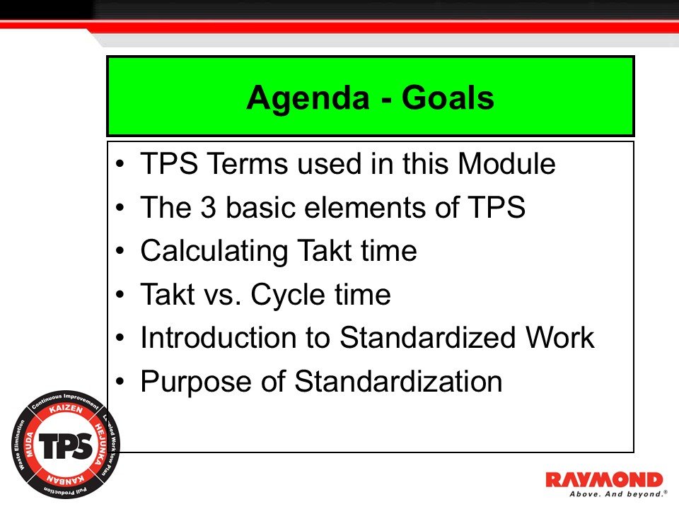
Figure 2. Agenda – Goals:
The six topics that introduce takt time, sequence, cycle time, and the purpose of Standardized Work.
Instructor Explanation
The purpose of this module is to build a strong foundation in the principles that support Standardized Work. Toyota treats Standardized Work as a method that integrates:
takt time
stable work sequence
correct level of standard work in process (SWIP)
To understand this method, participants must first learn the TPS terms and concepts that shape how work is designed, observed, and improved.
The module begins with essential TPS terminology. These terms frame the thinking behind flow, quality, and stability. Understanding this vocabulary allows participants to recognize how the elements of the Toyota Production System work together to support predictable performance and continuous improvement.
Next, the module introduces the three basic elements of standardized work, which create the structure that stabilizes work and makes abnormalities visible. Participants will learn:
why takt time sets the correct pace of work
why standardized sequence defines the safest and most efficient operator motion
why SWIP is required to maintain flow
The third learning objective is to understand how to calculate takt time. Takt time establishes the required rate of production to meet customer demand. Participants will learn the calculation method and how takt time is used as the baseline for designing work.
The module then explains the difference between takt time and cycle time. This is a critical TPS concept:
Takt time — pace required by the customer
Cycle time — observed time to complete the work
The gap between these two exposes instability, waste, or imbalance.
After these foundations are in place, the module provides an introduction to Standardized Work itself. Participants learn why Standardized Work is essential for stabilizing operations, supporting problem solving, and enabling kaizen.
The section concludes with a review of the purpose of standardization and how clear standards make abnormalities visible.
This agenda prepares participants for the detailed sections that follow. Each topic builds the capability needed to understand, create, and improve Standardized Work in a production environment.
Visual Reference
Slide: Agenda – Goals
Purpose: Provides the outline for the module and highlights the six core topics participants learn before applying Standardized Work.
Instructor Notes
Reinforce that the agenda follows Toyota’s teaching logic:
terms → takt → sequence → SWIP → purposeEmphasize that takt time and cycle time must be understood before any discussion of work sequence.
Clarify that this ordering reflects how Toyota develops capability inside plants.
Toyota Terms
Introduction
This section introduces two foundational Toyota Production System terms that must be understood before learning Standardized Work. These terms define the structure of work and the conditions required to stabilize production flow.
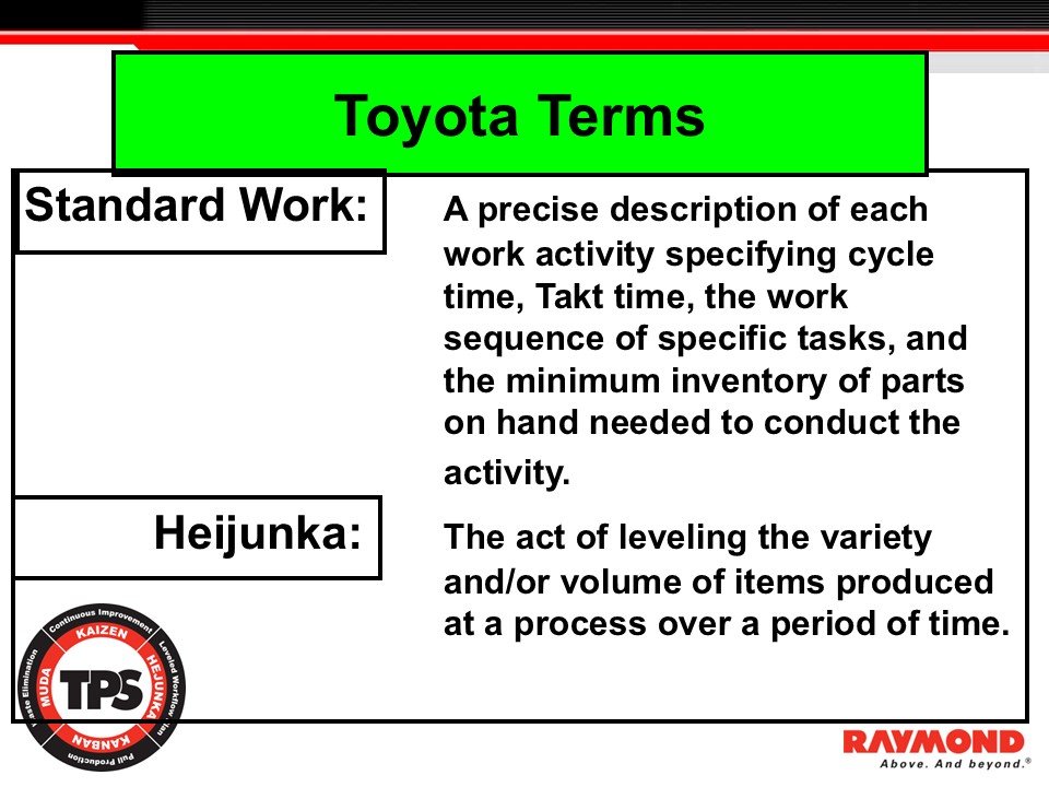
Figure 3. Toyota Terms:
Standardized Work defines the precise, safest, and most efficient method for performing the work.
Heijunka levels production volume and mix to stabilize the workload and support flow.
Instructor Explanation
Toyota uses precise terminology to describe the structure of work and the conditions required to build flow. Understanding these terms is essential because they form the basis for designing, evaluating, and improving production processes. The first term is Standardized Work. The second is Heijunka.
Standardized Work is the precise and current definition of how work is performed. It specifies:
the cycle time
the takt time
the repeatable sequence of steps
the minimum amount of in-process inventory required to maintain flow
This definition provides the anchor for stability. When the work sequence is unclear or performed differently each time, abnormalities cannot be seen. Without clarity in method, there is no baseline for improvement. Standardized Work establishes the normal operating condition so leaders and operators can identify any deviation immediately.
Heijunka is the act of leveling production. It balances volume and mix over time so the work can be performed at a consistent pace. Leveling is essential in TPS because unevenness creates instability, increases operator burden, and disrupts flow. When production schedules fluctuate, the work sequence cannot stabilize and takt time cannot be applied effectively. By leveling demand, Heijunka creates the conditions required for Standardized Work to function.
Together, Standardized Work and Heijunka define both the method of performing the work and the stability of the workload. Without these terms, it is not possible to understand the connection between takt time, flow, and improvement. These definitions support every method introduced later in the module.
Visual Reference
Slide: Toyota Terms
Purpose: Defines Standardized Work and Heijunka as foundational TPS concepts that must be understood before applying the three elements of Standardized Work.
Instructor Notes
Reinforce that Standardized Work is always the best known method at this moment.
Stress that Heijunka must be established before flow can stabilize.
Clarify that leveling is not optional, it is a precondition for real Standardized Work.
Use examples of uneven demand to show why work cannot stabilize without Heijunka.
The Three Basic Elements of TPS
Introduction
This section introduces the three foundational elements that define how work is paced, performed, and stabilized inside the Toyota Production System. These elements are required to create the baseline condition for Standardized Work.
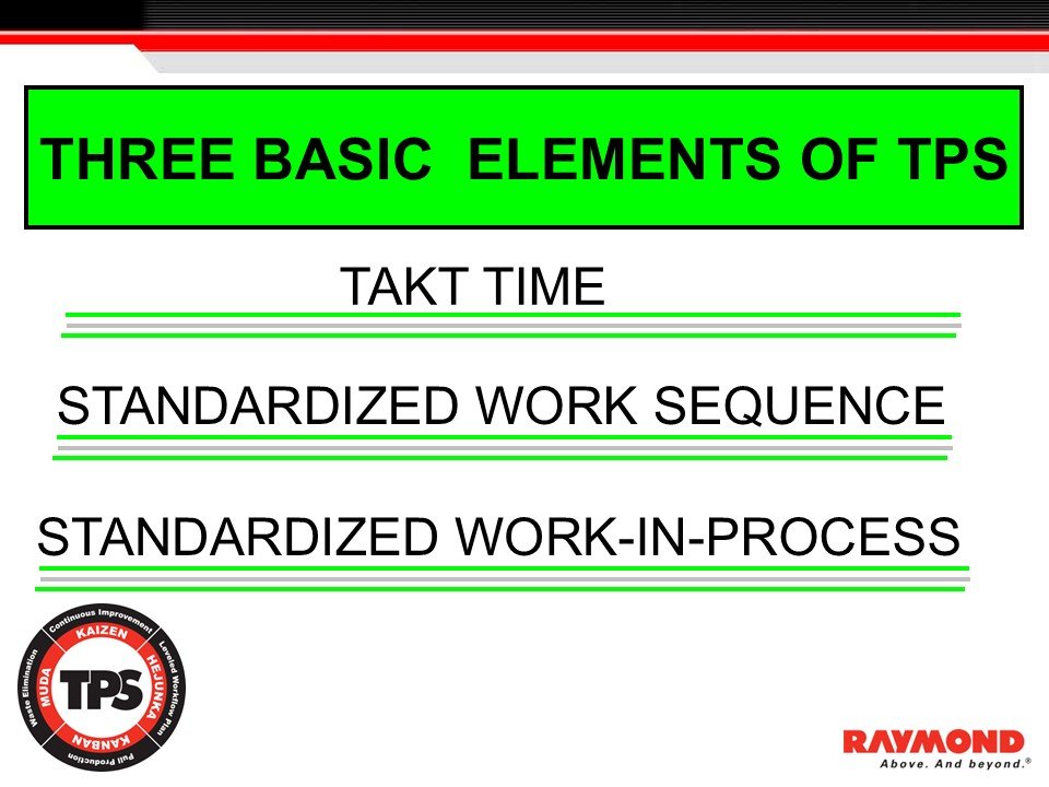
Figure 4: The Three Basic Elements of TPS
The three components that define the structure and stability of Standardized Work.
Instructor Explanation
The Toyota Production System is built on clarity, stability, and repeatable methods. The three elements presented here are the core building blocks that allow work to be performed consistently and evaluated objectively.
Takt Time
Takt time defines the pace of production required to meet customer demand. It is calculated by dividing the available operating time by the required output. Takt time becomes the rhythm of the process. Without takt time, work cannot be aligned with customer requirements and process variation becomes difficult to detect.
Takt time is the reference point used when designing work sequences, balancing workloads, and confirming whether the work is performed at the correct pace.Standardized Work Sequence
The standardized work sequence is the precise order of steps an operator follows to perform the work. The sequence defines the safest and most efficient method for completing each task.
When operators follow different sequences, variation is hidden and improvement cannot be measured. A clear and repeatable work sequence allows leaders and operators to see variation, confirm adherence, and identify opportunities for improvement.Standardized Work-in-Process (SWIP)
Standardized work-in-process defines the minimum number of units required between steps to maintain flow. Without sufficient in-process stock, the system will starve or block. Too much stock creates waste and hides instability.
Correctly set SWIP levels ensure smooth handoff between processes and support stable performance at takt time.
Together, takt time, sequence, and SWIP form the baseline condition of the process. When these elements are defined, maintained, and followed, abnormalities become visible and meaningful improvement becomes possible. Without these elements, Standardized Work cannot function and the process cannot support TPS principles.
Visual Reference
Slide: Three Basic Elements of TPS
Purpose: Shows the three components that define the structure and stability of Standardized Work.
Instructor Notes
The three elements must be established together.
Takt time is the reference for all three.
Sequence is the baseline for observing variation.
SWIP must be defined at the minimum required level.
Takt Time – Understanding the Pace of Production
This section explains how takt time is calculated and why it defines the production pace required to meet customer demand within the Toyota Production System.
The image below shows an example of a takt time calculation using different production requirements. It demonstrates how changes in customer demand directly adjust the takt time available to complete each unit.
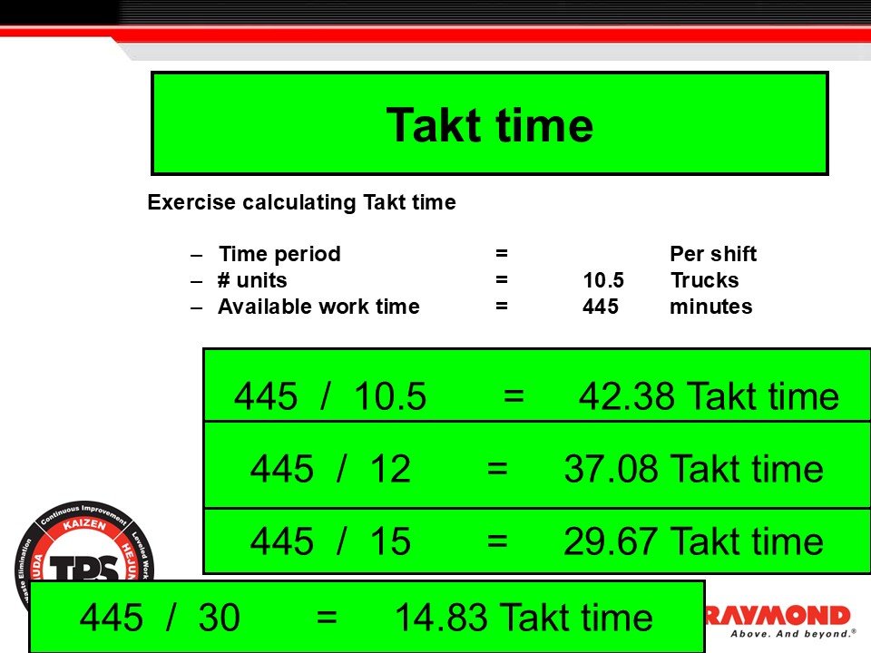
Figure 5: Takt Time Calculation
Shows how changing customer demand adjusts the takt time available per unit and sets the required production pace.
Instructor Explanation
Takt time is the time available per unit required to meet customer demand. It aligns production with the rate at which the customer receives the product. When takt time is understood and applied correctly, the process becomes synchronized, abnormalities become visible, and leaders can design work that maintains flow without overburden.
Takt time is calculated by dividing the available operating time by the number of units required. In the example shown, a shift provides 445 minutes of operating time. When the requirement is 10.5 trucks per shift, the takt time is 42.38 minutes. The same method applies when demand changes. Increasing demand reduces takt time. Decreasing demand increases takt time. This relationship ensures that the production system adjusts to customer needs rather than producing based on internal assumptions.
Takt time is expressed as time per piece. This is intentional. Operators must know how much time they have to complete each cycle. Expressing takt time correctly creates focus on the allowable time to perform the sequence before repeating it. It also allows team leaders to see whether work aligns to takt or drifts from the standard.
Cycle time is different. Cycle time is the observed time for an operator to complete all work elements and return to the starting point. It includes loading, unloading, walking, motion, and machine interaction. Cycle time is measured by direct observation at the workstation. When cycle time is higher than takt time, the process cannot keep up with demand. When cycle time is significantly lower than takt time, the operator may be underloaded or the line may not be balanced.
A stable process targets cycle times at or below takt time. A common goal is to set cycle time at approximately 90 percent of takt time. This leaves capacity for recovery, minor adjustments, and small interruptions without creating delay or overburden.
Understanding takt time is essential before learning standardized work sequence and in-process stock. These methods depend on a clear production pace. Without takt time as a reference, the system cannot be balanced, flow cannot be maintained, and abnormalities remain hidden.
Instructor Notes
– Reinforce that takt time is always based on customer demand.
– Clarify that time per piece is intentional to guide operator pacing.
– Emphasize the distinction between takt time and cycle time.
– Highlight that cycle time must be confirmed by direct observation.
Takt Time Example
Introduction
This section demonstrates how takt time applies across multiple processes in a production system. It shows how different components feeding into a final assembly must align their output to the takt time of the main process.
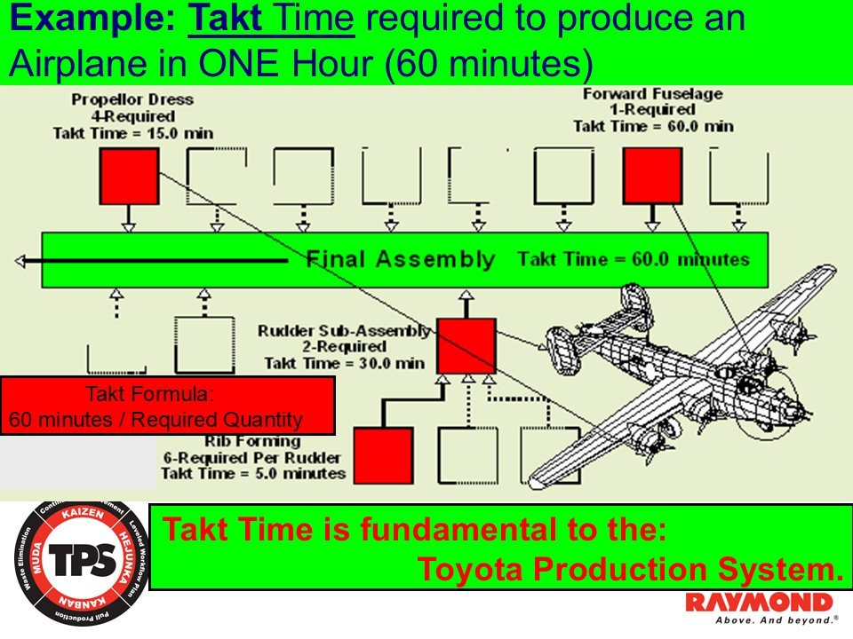
Figure 6. Example: Takt Time Required to Produce an Airplane in One Hour
Shows how required quantity drives takt time at each feeder operation supporting a sixty minute final assembly takt.
Takt time establishes the pace at which products must be completed to meet customer demand. In this example, the system is designed to produce one airplane every sixty minutes. The takt time for the final assembly process is therefore sixty minutes. Every upstream operation must align its production rate so that the final assembly process receives components at the correct pace without interruption.
The forward fuselage is required at a rate of one unit per aircraft. Its takt time is sixty minutes. This aligns directly with the final assembly takt time. The rudder sub assembly requires two units per airplane. To support final assembly at sixty minutes per aircraft, the rudder sub assembly must produce at a takt time of thirty minutes. Producing two units every sixty minutes ensures that the final assembly process receives both rudders on time.
Propeller dress requires four propellers per aircraft. This increases the required production pace. To deliver four units every sixty minutes, the propeller dress operation must produce at a takt time of fifteen minutes. Six ribs are required to support this assembly. The rib forming takt time must therefore be five minutes since six pieces must be completed every sixty minutes.
This example shows how takt time cascades through the system. The final assembly takt time determines the required pace for all feeder lines. By calculating takt time at each production step, leaders ensure component availability, maintain flow, and prevent bottlenecks or excess inventory. Each process produces exactly what is required when it is required. This aligns the entire value stream with customer demand.
Takt time creates synchronization across all production levels. When each process operates at its required takt time, the system functions as a connected flow rather than isolated operations. This supports stability, reduces waste, and enables clear identification of abnormalities.
Takt Time vs Cycle Time
Introduction
This section explains the difference between takt time and cycle time. Understanding this distinction is essential for evaluating stability, balancing work, and identifying abnormalities in the production process.
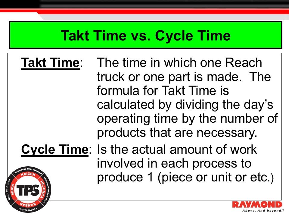
Figure 7. Takt Time vs Cycle Time
Defines the difference between takt time and cycle time and shows how both measures determine whether the process meets customer demand.
Takt time and cycle time are two of the most important measures in the Toyota Production System. They are often confused, but each serves a different purpose. Takt time sets the required pace of production based on customer demand. Cycle time reflects the actual time needed to complete the work. Comparing the two reveals whether the process can meet demand, whether work is balanced, and whether improvement is required.
Takt time is calculated by dividing the available operating time by the number of units required. It represents how much time is allowed to produce one unit. Takt time is driven entirely by customer demand and is used to design line balance, determine staffing, and identify the correct workload for each operator. It establishes the rhythm of production.
Cycle time is the actual time required for one operator or one machine to complete the full sequence of work. It is measured at the workstation by direct observation. Cycle time includes all elements of work such as handling, loading, unloading, walking, and interacting with equipment. Cycle time reflects how the process actually performs, not the pace required by demand.
A stable process must have cycle time equal to or less than takt time. When cycle time is greater than takt time, the process cannot meet demand. When cycle time is significantly less than takt time, the operator may be underloaded or the line may not be balanced. This indicates waste and unused capacity.
Takt time and cycle time work together to reveal abnormalities. Takt time shows what is required. Cycle time shows what is actually happening. The gap between the two is where kaizen begins. By reducing the difference, leaders stabilize the process and build the foundation for Standardized Work.
Purpose of Standardized Work
Introduction
This section explains why Standardized Work is essential for stabilizing production and preventing the three sources of process variation. It establishes the connection between Standardized Work and the conditions required for meaningful kaizen.
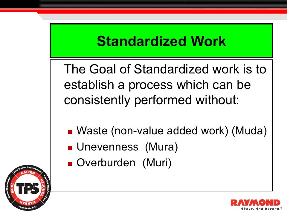
Figure 8. Purpose of Standardized Work
Shows that the goal of Standardized Work is to eliminate muda, mura, and muri and create a stable baseline for improvement.
Standardized Work exists to create a stable and repeatable production process. A stable process can be performed the same way every time and does not depend on individual habit or preference. Without stability, it is impossible to see abnormalities, maintain flow, or sustain improvement.
The goal of Standardized Work is to eliminate the three forms of process variation. The first is waste, or muda. Waste is non value added activity that consumes time and resources without contributing to the final product. When work is performed inconsistently, waste increases and becomes difficult to see. Standardized Work removes this variation by defining the correct method.
The second form of variation is unevenness, or mura. Unevenness creates instability by causing work to fluctuate between high and low workloads. This disrupts rhythm, increases waiting, and forces operators to adjust their pace throughout the shift. Standardized Work establishes a consistent work sequence that aligns with takt time. This reduces variation in operator pace and ensures that the workload is balanced.
The third form is overburden, or muri. Overburden places unnecessary physical or mental strain on operators and equipment. It results from unclear work methods, poor layout, or unbalanced cycles. When work is standardized, the sequence becomes predictable and manageable. Operators are protected from excessive burden and can perform the work safely and efficiently.
Standardized Work is also the foundation for kaizen. Improvement is only possible when the current method is documented and followed. If work is performed differently each time, leaders cannot measure the impact of improvements or confirm whether changes were effective. Standardization creates a baseline that reveals abnormalities and highlights opportunities for improvement.
Leaders are responsible for defining Standardized Work, confirming adherence, and updating the standard when improvements are proven. Standardized Work must not remain static. It is revised whenever kaizen, equipment improvements, or method changes create a better approach. Each revision becomes the new baseline for further improvement.
When these conditions are present, Standardized Work strengthens quality, reduces cost, and improves safety. It creates the stability required for flow and aligns the work with the principles of the Toyota Production System.
Elements of Standardized Work
Introduction
This section explains why documenting the current method is essential for establishing a baseline. It shows how Standardized Work makes abnormalities visible and why it is the starting point for continuous improvement.
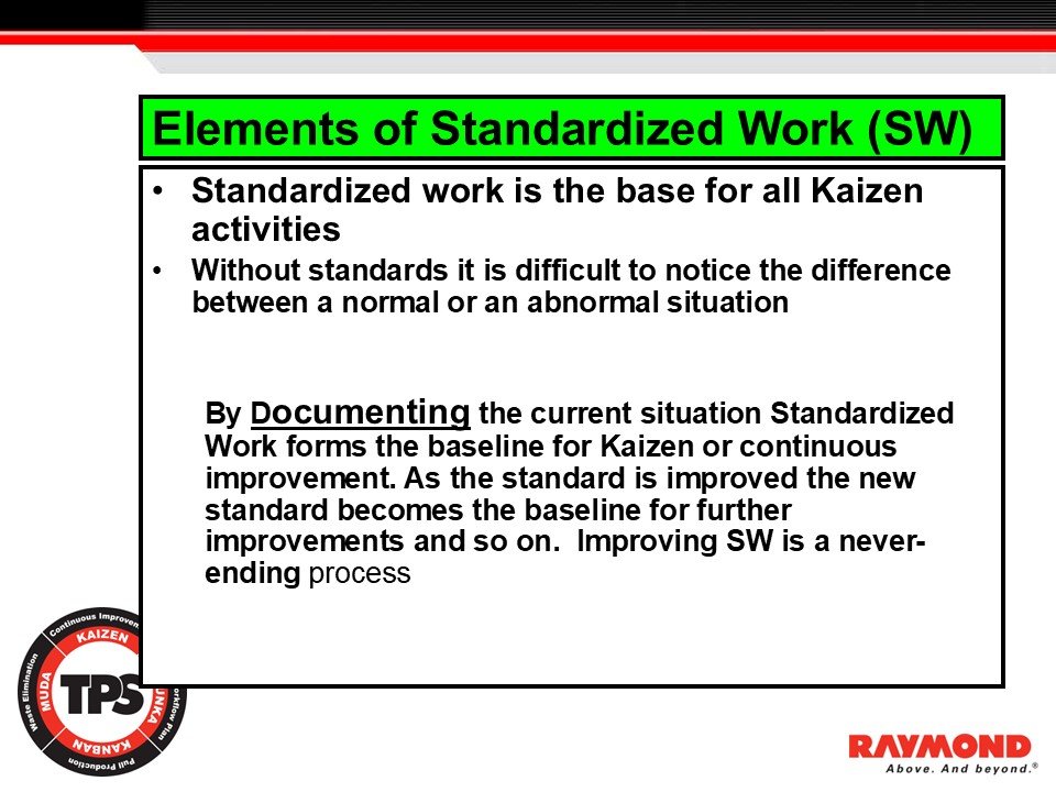
Figure 9. Elements of Standardized Work:
Shows that Standardized Work forms the baseline for kaizen by documenting the current method and establishing a clear reference condition.
Standardized Work is the base for all kaizen activity. Improvement can only occur when the current method is known, documented, and followed. Without a defined standard, it is difficult to identify abnormalities. Leaders and operators cannot distinguish between a normal condition and an abnormal one when work methods vary from person to person or shift to shift.
Documenting the current situation creates the baseline. This baseline becomes the reference for evaluating performance, identifying waste, and confirming whether the process is stable. When the standard is unclear, improvement cannot be measured. When the standard is not followed, abnormalities become hidden and problems are misinterpreted as normal variation.
As the process is improved, the standard must be updated. Each improvement produces a new best method. This new method becomes the next baseline for further improvements. Standardized Work is therefore a living system. It evolves as the organization learns, as equipment changes, and as kaizen activities refine the work.
Improving Standardized Work is a never ending process. Each improvement strengthens quality, reduces cost, and increases safety. Each revision builds capability and deepens understanding of the work. The cycle of documentation, confirmation, and revision ensures that improvement becomes part of daily operations rather than a one time effort.
Standardized Work also ensures that operators perform the job safely and consistently. It defines the correct motion, sequence, and conditions for performing the work. When these conditions are followed, variation decreases and the process becomes more predictable. When deviations occur, leaders can identify the cause quickly because the normal method is clear.
This discipline supports the principles of the Toyota Production System. By documenting the standard and maintaining it through daily management, the process becomes stable enough to expose waste and unevenness. From this baseline, kaizen becomes meaningful and sustainable.
Abnormality and the Role of Standardization
Introduction
This section explains the connection between Standardized Work and the ability to detect abnormalities. It reinforces that standardization is the starting point of TPS because it defines what is normal and makes deviations immediately visible.
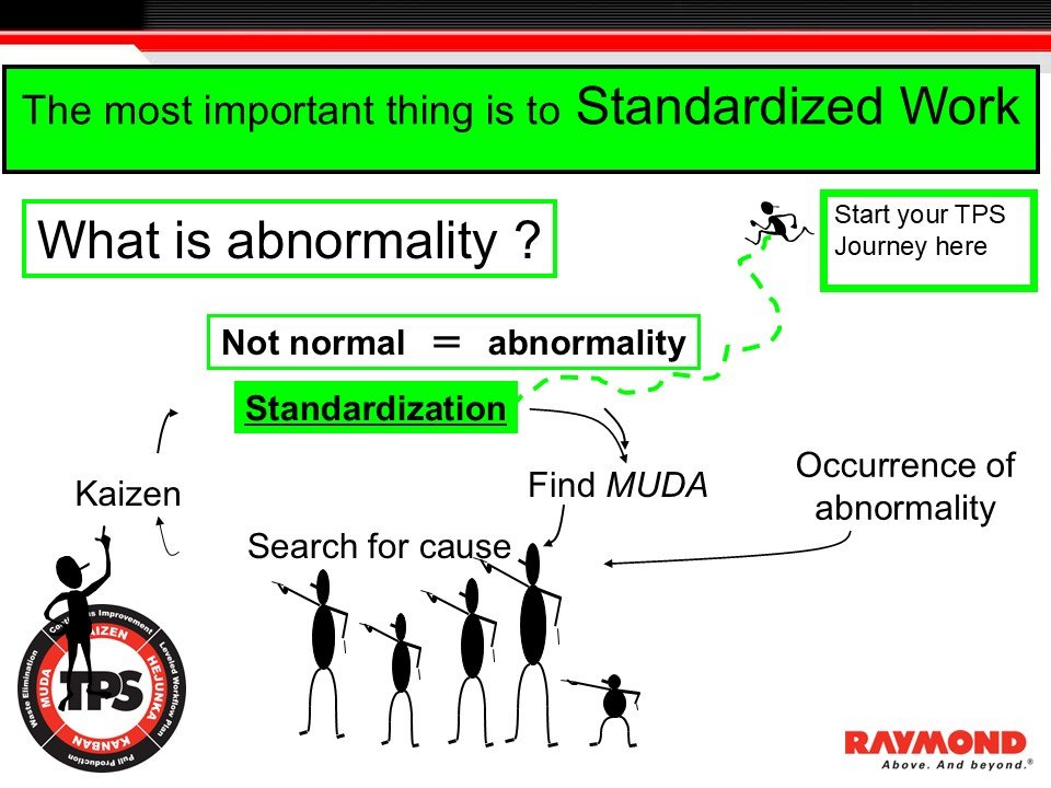
Figure 10. Abnormality and the Role of Standardization
Shows how defining the standard creates visibility for abnormal conditions, enabling waste identification and kaizen.
In the Toyota Production System, the most important starting point is to establish Standardized Work. Without a clear standard, it is impossible to recognize when something is abnormal. An abnormality is any condition that differs from the defined normal method. If the normal method is unclear or inconsistent, abnormal conditions blend into daily work and remain hidden.
Standardization makes the normal condition visible. Once the normal condition is established, any deviation can be recognized as an abnormality. This visibility is essential for maintaining safety, quality, cost, and delivery performance. When an abnormality occurs, leaders and operators can quickly identify the source and begin problem solving.
The sequence shown in this slide illustrates the basic logic. First, the standard must be defined. This creates the baseline for what is normal. When work does not follow the standard, an abnormality occurs. Operators and team leaders then search for the cause. This leads to identifying waste and understanding why the deviation occurred. Once the cause is identified, kaizen activity can correct the condition and improve the process.
This cycle repeats continuously. Standardization is not a one time activity. When an improvement is confirmed, the new method becomes the updated standard. This new standard defines the next level of normal. Abnormalities become visible again when the process deviates from the improved method. This cycle drives learning and strengthens the capability of the organization.
Starting the TPS journey with Standardized Work ensures that problems are not hidden and that improvement is directed at the root causes. It creates a clear line between normal and abnormal conditions and supports effective problem solving.
Leader’s Role in Standardized Work
Introduction
This section explains the responsibilities of leaders in creating, confirming, and continuously improving Standardized Work. It clarifies why leadership ownership is essential to maintain stability and support kaizen.
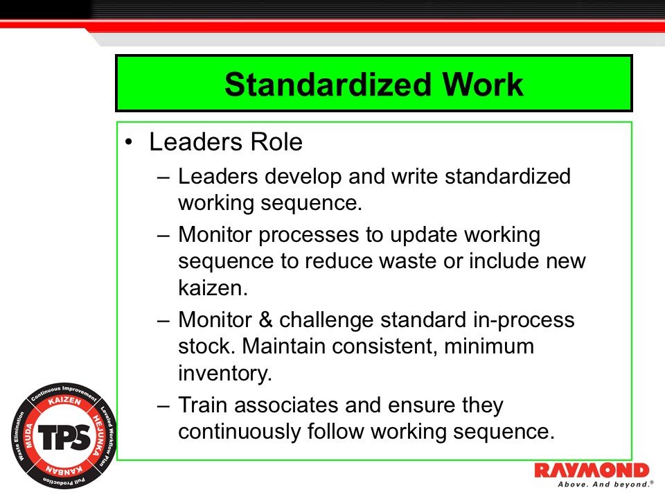
Figure 11. Leader’s Role in Standardized Work
Shows leadership responsibilities for defining, monitoring, updating, and training to Standardized Work.
Leaders have a critical role in developing and sustaining Standardized Work. Their responsibility begins with defining the work sequence. Leaders document the correct method, specify takt time, identify the required in process stock, and ensure the sequence reflects the safest and most efficient way to perform the work. This documented standard becomes the baseline that operators follow and that leaders use to confirm performance.
Once the standard is established, leaders must monitor the process to ensure it is being followed. Confirmation is a daily activity. It verifies that operators are performing the work according to the defined method and that the process is aligned with takt time. When deviations occur, leaders respond by identifying the cause and restoring the standard. This maintains stability and prevents problems from becoming hidden.
Leaders are also responsible for updating Standardized Work when improvement occurs. When takt time changes due to demand, when production requirements shift, or when kaizen activities improve the method, the standard must be revised. This includes adjusting work allocation, confirming load balance, and updating in process stock where needed. Leaders ensure that the updated method becomes the new baseline.
Maintaining consistent, minimum in process stock is another leadership responsibility. Excess inventory hides instability, while insufficient inventory disrupts flow. Leaders confirm that stock levels support takt time and challenge any conditions that create imbalance.
Training is a core leadership function. Operators must understand the work sequence and the reasons behind it. Leaders train team members to follow the method, recognize abnormalities, and participate in improvements. They also include new team members in kaizen and teach them how to evaluate the process using the standard.
Leadership commitment to Standardized Work strengthens the daily management system. It ensures that problems are visible, improvements are sustained, and the process remains aligned with TPS principles.
Purpose of Standardization
Introduction
This section explains why standardization is required to build a stable process, evaluate performance, and establish the foundation necessary for kaizen.
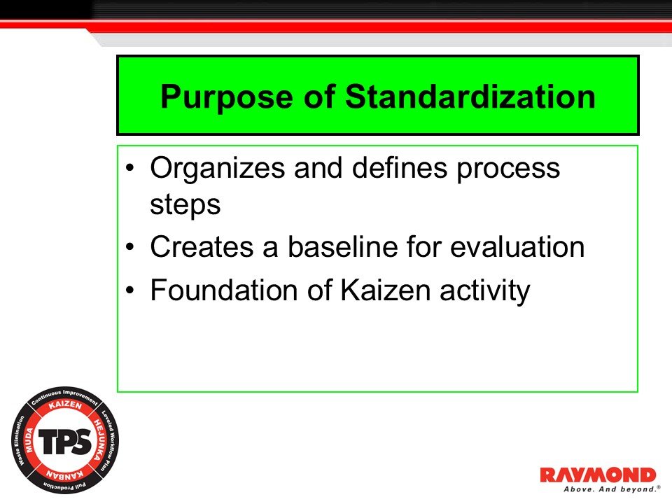
Figure 12. Purpose of Standardization
Shows how standardization organizes process steps, establishes a baseline, and supports kaizen activity.
Standardization organizes and defines the steps of a process. When work is not organized or clearly defined, operators create their own methods, often based on habit or preference. This leads to variation, uneven results, and difficulty identifying problems. By organizing the steps, standardization eliminates confusion and creates a clear and repeatable method for performing the work.
Standardization also creates the baseline for evaluation. A baseline is necessary because improvement depends on knowing the current condition. Without a defined standard, leaders and operators cannot determine whether the process is performing correctly or drifting into abnormal conditions. A documented and visible standard allows teams to evaluate work against an agreed method and identify where variation occurs.
Standardization forms the foundation for kaizen. Improvement is meaningful only when the starting point is known. When a standard exists, changes can be measured, verified, and sustained. Each improvement produces a new standard that becomes the next baseline. This cycle ensures that kaizen is systematic and disciplined, not random or inconsistent.
The purpose of standardization is not to limit creativity or restrict operators. It is to create clarity, stability, and a shared understanding of the method. When these conditions exist, problems become visible, improvement becomes possible, and the process aligns with the principles of the Toyota Production System.
Types of Standardized Work
Introduction
This section introduces the two primary types of Standardized Work used in TPS. It explains when each type applies and why different work conditions require different formats to define the method correctly.
Figure 13. Types of Standardized Work:
Introduces Type I and Type II Standardized Work and clarifies their appropriate use.
Toyota uses two main types of Standardized Work to document and stabilize production activities. Each type is designed for a specific kind of work environment and motion pattern. Using the correct type ensures that the work sequence, timing, and in process stock are documented in a way that reflects how the work is actually performed.
Type I Standardized Work is used for most standard activities. This format applies when the operator performs work within a defined workstation and the motion pattern is contained. The sequence is clear, the timing is repeatable, and the operator’s path is limited to a small area. Type I is suitable for assembly operations, machine operations, and processes where the operator is not required to walk between multiple stations. It provides a clear definition of cycle time, sequence, and in process stock within a bounded workspace.
Type II Standardized Work is used when the operator is in motion. This type applies to processes where the operator moves between work areas, machines, or stations as part of the sequence. Examples include mobile tasks, long walking paths, and operations spread across multiple locations. Type II captures hand work, machine time, walking, and waiting in a single view. It makes it possible to see the interaction between the operator’s movement and the equipment cycle. This format is essential for identifying long walking distances, unbalanced machine loads, and inefficiencies hidden in motion.
Choosing the correct type of Standardized Work ensures that problems become visible. When Type I is used for work that requires movement, critical variation remains hidden. When Type II is used for stable, stationary work, the format becomes unnecessarily complex. Matching the format to the nature of the work is part of good TPS practice and allows leaders to analyze the process correctly.
Understanding both types prepares participants for the detailed examples that follow, including Type II charts, Standardized Work Combination Tables, and Standardized Work Charts.
Type II Standardized Work – Line 2 Overview
Introduction
This section introduces a real production example of Type II Standardized Work. It shows how Type II is applied in environments where operators move between stations, manage multiple processes, and support a fast production pace aligned to takt time.
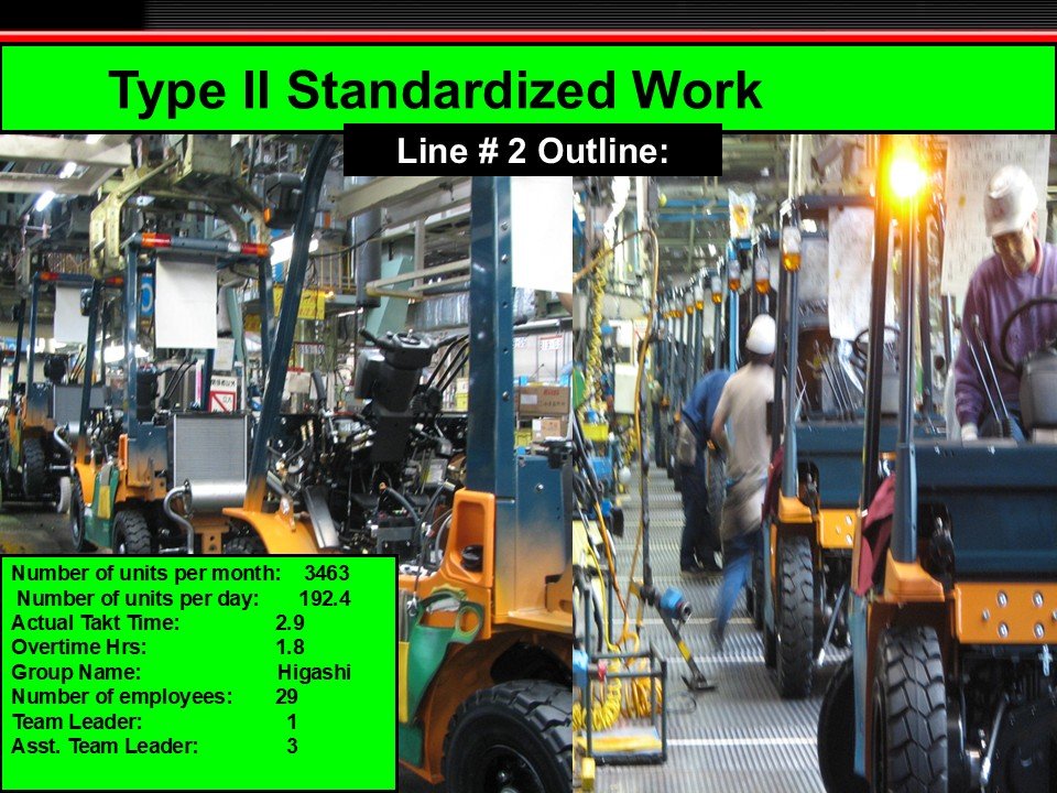
Figure 14. Type II Standardized Work – Line 2 Overview
A high-volume production line example requiring Type II Standardized Work due to operator motion, multiple stations, and takt-paced flow.
Type II Standardized Work is required when operators perform work while in motion. Unlike Type I, which applies to stationary work contained within a single workstation, Type II is designed for environments where operators walk, transition between stations, interact with multiple machines, or support several sequential operations. This format captures the interplay of hand work, machine waiting, walking time, and takt time in a single view.
The Line 2 production example shows a high-volume assembly operation producing 3463 units per month with a requirement of 192.4 units per day. The takt time for this line is 2.9 minutes. This short takt time means that every movement, reach, and transition must be defined, visible, and structured to maintain flow. Any deviation from the sequence immediately creates imbalance and disrupts the line.
The workforce structure includes twenty nine employees supported by one team leader and three assistant team leaders. This level of leadership support is necessary in fast-paced environments. Abnormalities appear quickly when takt time is tight, and leaders must confirm sequence adherence, support immediate problem solving, and manage in process stock throughout the shift. Their presence stabilizes the line and helps sustain the takt rhythm.
The image illustrates typical conditions that require Type II documentation. Operators walk between tasks, interact with equipment, and adjust their pace to match the line. These motion-based activities cannot be captured accurately using Type I charts. Type II Standardized Work reveals long walking paths, unbalanced load distribution, unnecessary motion, and instability that would otherwise remain hidden. This visibility is essential for effective kaizen.
Overtime is listed at 1.8 hours, indicating that the line experiences pressure from demand. Precise standardized work is necessary to prevent overburden, protect operator safety, and maintain consistent performance. When takt time is aggressive, any inefficiency contributes to muri, mura, and increased waste. Type II charts provide the clarity needed to identify improvement opportunities and support real load balancing.
This section prepares participants for detailed Type II worksheets, including the Standardized Work Combination Table and Standardized Work Chart. These tools show motion, timing, and machine-interaction patterns in a structured format, enabling leaders to evaluate the process objectively and sustain TPS flow conditions.
Instructor Notes
Reinforce that Type II is required when operators walk or transition between stations.
Highlight that tight takt time exposes instability quickly and requires disciplined sequence adherence.
Emphasize the importance of leadership presence in fast-paced environments.
Use this example to transition into detailed Type II worksheets in the next section.
Type II Standardized Work Sheet – Battery Cycle Time (Line 2, Station 7R)
Introduction
This section introduces a real Type II Standardized Work Sheet from a high-volume Toyota assembly environment. It shows how motion, sequence, distance, and takt-based timing are captured in a single view to expose waste and support motion kaizen.
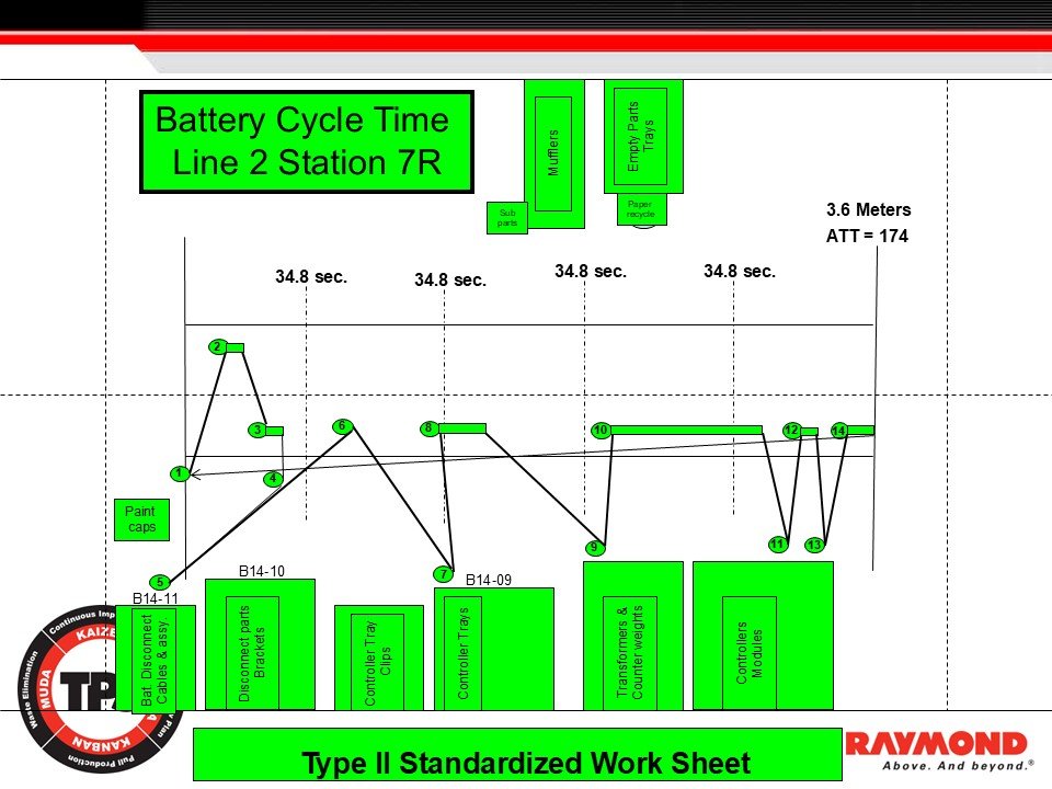
Figure 15: Type II Standardized Work Sheet – Battery Cycle Time (Station 7R)
Visualizes operator motion, sequence, distance, and takt-based timing for the Battery Cycle Time process on Line 2.
Type II Standardized Work is required when operators move across space as part of the job. The Battery Cycle Time example from Line 2 Station 7R demonstrates how Toyota documents work in motion inside a fast takt environment. The station operates at a takt time of 34.8 seconds, with the operator traveling 3.6 meters during the cycle. The worksheet captures motion, timing, and the sequence of work in a single structured chart.
The numbered points on the chart represent each work element. These points connect to show the physical path of the operator as they move between component locations such as battery cable disconnect, bracket removal, controller trays, clips, transformers, counterweights, and controller modules. This visual sequence allows leaders to see whether the path is efficient and whether motion aligns with takt time.
Vertical and horizontal reference lines break the cycle into 34.8-second takt segments. These segments show whether the operator can complete the full sequence within the takt window. When work consistently extends beyond this window, the process becomes unstable and requires rebalance. The worksheet also lists the available time per takt (ATT = 174 seconds), which provides a reference for load distribution across operators or stations.
Type II visualizations expose waste that Type I documents cannot capture. Long walking paths, unnecessary loops, and inefficient material placement become visible when the operator’s movement is mapped. In this example, the sequence shows several cross-station loops that indicate opportunities for layout improvement, material relocation, or sequence redesign. These opportunities are often hidden until motion is documented visually.
Leadership uses Type II worksheets to evaluate work distribution, confirm motion stability, and identify risk areas such as overburden or uneven work pacing. Because operators must move quickly within a short takt time, even small inefficiencies can disrupt flow. The worksheet provides a factual basis for kaizen, allowing teams to reduce walking distance, streamline motion, and improve ergonomics.
This example prepares participants for deeper motion analysis, including combination tables and multi-process studies. Type II Standardized Work is one of the most effective tools for exposing hidden waste and supporting continuous improvement in environments where motion is integral to the work.
Type II Standardized Work Sheet – Engine Cycle Time (Line 2, Station 7R)
Introduction
This section presents a Type II Standardized Work Sheet for the engine installation and related component work at Line 2 Station 7R. It shows how operator movement, distance, timing, and work elements are captured together to reveal waste and opportunities for improvement.
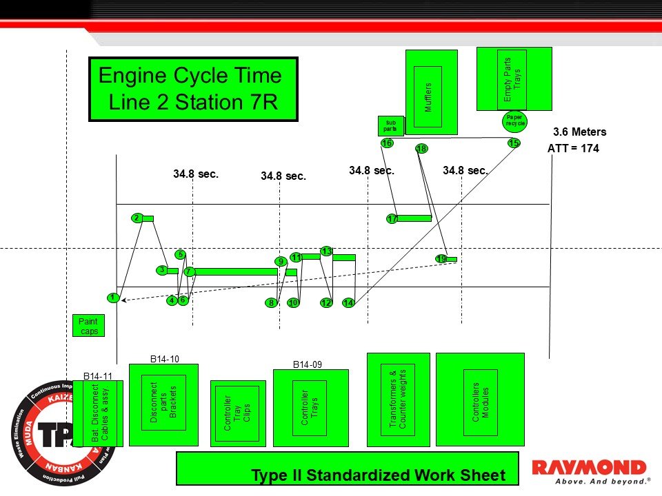
Figure 16: Engine Cycle Time – Type II Standardized Work (Station 7R)
Shows the operator’s motion path, component locations, and takt-segmented timing for the engine installation sequence on Line 2.
Type II Standardized Work is required wherever operators move across space as part of the work sequence. The Engine Cycle Time chart for Line 2 Station 7R illustrates how Type II captures motion, timing, and sequence variation within a single document. This environment requires structured analysis because the operator performs multiple tasks across several meters of workspace and interacts with components located at different points on the line.
The takt time for this station is 34.8 seconds. The operator travels 3.6 meters within each cycle, and the chart segments the sequence into takt-based intervals. These segments show how the operator’s movements and tasks must be completed within the takt window to maintain flow. The lines connecting each numbered element represent the operator’s physical path, including hand work, walking motion, and interactions with machines or components. This combined motion-and-time representation reveals patterns that are not visible when element times are listed separately.
The lower portion of the chart shows the component locations required for this station. These include battery disconnect brackets, controller trays, controller clips, transformers, counterweights, and controller modules. Additional locations for mufflers, sub parts, and recycling materials are positioned farther away from the primary work area. The operator must travel to these locations to complete elements 15 through 19, increasing total motion and creating variation within the cycle.
Type II documentation exposes these conditions immediately. Multiple loops and crossovers appear in the operator’s path. These indicate that the physical layout forces unnecessary movement. Tasks located outside the main flow area create instability because any delay during these extended paths can push the operator beyond takt time. When variation occurs, the sequence becomes more difficult to maintain and abnormalities become more frequent.
The chart also lists the Available Time per Takt (ATT = 174 seconds). Leaders use ATT to distribute workload across operators or confirm whether tasks exceed capacity. When the operator’s travel distance is long or the sequence contains unnecessary motion, ATT is consumed quickly, leaving little margin for minor interruptions.
This example shows how Type II Standardized Work is used to evaluate motion waste, distance, layout design, and sequence logic. It highlights opportunities to shorten routes, reposition components, reduce physical burden, and stabilize the sequence. Before kaizen can improve these conditions, the real method must be captured accurately through Type II documentation. This sheet provides the starting point for that improvement.
Instructor Notes
Reinforce that Type II is required whenever walking distance affects takt time.
Highlight that long paths and crossovers often represent hidden waste.
Emphasize that layout design and component location must support takt time.
Use this chart to introduce motion kaizen and standardized layout principles.
Kaizen Example – Line 2 Takahama
Introduction
This section shows how Standardized Work reveals small sources of waste that can be removed through kaizen. The example from Line 2 in Takahama demonstrates how a simple improvement in part presentation produced a two-second time reduction and reduced operator burden.
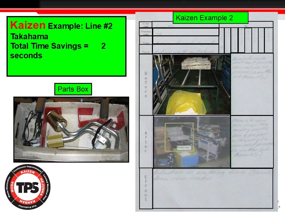
Figure 17: Kaizen Example – Line 2 Takahama (2-Second Improvement)
Shows how improved part presentation removed small motion loss and produced a verified two-second cycle time reduction.
Kaizen often begins with small improvements that remove friction from the work. This example from Line 2 in the Takahama plant shows how a two-second time reduction was achieved by improving part presentation. Although the change is small, it reflects the Toyota practice of using Standardized Work to make waste visible and support continuous improvement.
Before kaizen, the parts were stored loosely in the box. The operator had to search, adjust position, and shift between components, resulting in multiple small motions that accumulated across each cycle. These motions were not obvious until the Standardized Work sequence made the path, reach, and timing visible.
The kaizen activity reorganized the parts box, relocated components, and improved the material presentation so the operator could retrieve each part with minimal motion. The after condition shows clear separation of items, reduced searching, and fewer reach adjustments. Even though the measured time savings is only two seconds, this reduction is meaningful across hundreds of cycles per shift.
The improvement also reduces operator burden and increases the stability of the process. Reducing motion helps operators follow the standardized sequence consistently, which strengthens takt adherence and reduces variation. Whenever kaizen changes the work, the Standardized Work document must be updated so the improvement becomes the new baseline.
This example demonstrates how small kaizen steps accumulate and strengthen flow, safety, and work stability. Improvements in part presentation, layout, and motion reduction are some of the most common and effective forms of TPS kaizen.
Instructor Notes
Reinforce that two-second improvements are significant at takt time.
Emphasize that improved part presentation is one of the most effective forms of kaizen.
Clarify that all improvements must be captured in updated Standardized Work.
Encourage teams to look for small motion losses that occur repeatedly in each shift.
Type II Standardized Work – Multi Station Overview (Line 2: Stations 4L, 5L, 6L, 7R)
Purpose of the Section
This section explains how Type II Standardized Work visualizes operator movement across multiple stations on Line 2. It shows how Type II reveals hand work, machine time, walking time, and wait time to support line balancing and improvement.
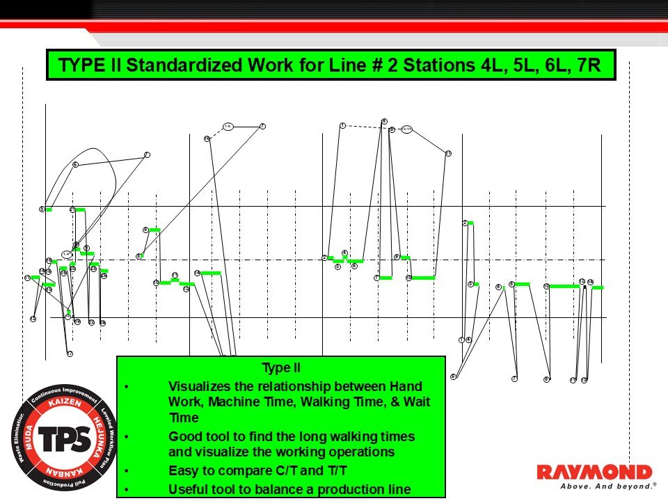
Figure 18: Multi Station Type II Standardized Work Chart
Operator motion, load, and timing across four stations using Type II Standardized Work.)
Type II Standardized Work is used when operators move across space as part of the work sequence. This example shows Type II applied across four stations on Line 2. These stations require operators to walk between points, perform hand work, load and unload equipment, and coordinate actions with machine timing. Because the work involves continuous operator motion, Type II is the correct format to document the method.
The chart shows each operator action as a numbered step. The horizontal axis represents time. The vertical axis shows the operator’s working position and movement between locations. By plotting each step in sequence, the chart reveals the complete pattern of operator motion. This includes hand work, machine interaction, walking, and waiting. When these elements are viewed together, leaders gain an accurate view of the system.
One purpose of Type II is to highlight long walking paths. Walking often becomes excessive in processes that evolved without structured layout planning. Type II charts make these paths visible. When walking consumes too much cycle time, the operator cannot maintain takt time. This reveals instability and signals the need for layout or material presentation kaizen.
The chart also shows the relationship between hand work and machine time. When operators must move between areas to load, unload, or observe machines, timing must be coordinated. Type II charts show whether machine cycles align with the operator sequence or whether delays create waiting conditions.
The green bars show the time required for each element or group of elements. This makes it possible to compare cycle time and takt time. When the element times exceed takt time, the station becomes unstable. When the times fall significantly below takt time, the operator may be underloaded or the sequence may require combination with additional tasks.
This multi station chart is useful for line balancing. When viewed as a system, it becomes clear when one station carries excess load while another has idle time. Leaders can adjust element allocation, redistribute load, and strengthen flow.
This example reinforces that Type II Standardized Work is not limited to a single operator at a single station. It is a method for analyzing motion, timing, and workload across several stations. It supports stable flow by making imbalance and motion waste visible.
Instructor Notes
• Type II is essential whenever operator walking affects takt time.
• Long walking paths often indicate hidden waste.
• Type II charts expose imbalance across stations.
• Use crossovers, long travel lines, and idle time as indicators of improvement opportunities.
Operator Activity Chart
Introduction
This section explains how the Operator Activity Chart visualizes operator workload, sequence, and movement across a complete cycle. It shows how the chart identifies imbalance, waiting, overburden, and motion waste that influence takt time and line stability.
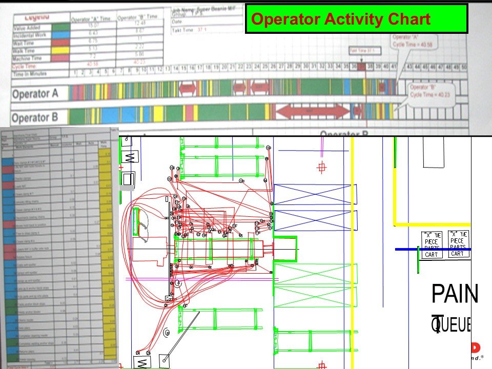
Figure 19: Operator Activity Chart – Visualizing Workload, Motion, and Balance
Shows operator workload distribution, motion paths, and cycle time comparison to identify imbalance and hidden waste.
The Operator Activity Chart is a core tool for analyzing work balance within a production line. It displays the full sequence of operator activities and classifies them by time category, allowing leaders to evaluate workload against takt time and identify variation that is not visible from element timing alone.
The chart contains two operators, Operator A and Operator B. Their activities are shown in a continuous timeline using a color-coded legend. Each color represents a specific category such as value added work, manual work, machine time, walking, and waiting. By viewing these categories together, leaders can immediately see the distribution of work and identify conditions such as overburden, excessive walking, or long waiting periods.
The chart makes it possible to compare operator cycle times directly. Operator A’s cycle time is approximately 40.58 seconds, while Operator B’s cycle time is approximately 40.23 seconds. These values are compared to takt requirements to determine whether the line is balanced. When operators differ significantly in cycle time, the line will experience instability, delays, or uneven output. The chart therefore supports the decision-making process for redistributing tasks or correcting layout issues.
The lower half of the slide includes a detailed motion map of the workstation. Red path lines show the actual movement taken by the operator during the cycle. Each numbered point corresponds to the sequence shown in the activity chart. This connection between time categories and physical motion makes it possible to identify long walking paths, crossovers, and inefficient loops in the layout.
The Operator Activity Chart also highlights the relationship between value added and non-value added time. When walking or waiting time appears in long blocks, leaders can trace the source directly to material presentation issues, work sequence variation, or layout constraints. These insights support targeted kaizen activity.
By combining the Operator Activity Chart with Type II Standardized Work and the motion layout, leaders obtain a complete view of the operator’s work content. This supports accurate line balancing, reveals hidden waste, and guides improvements in layout, ergonomics, and material flow.
Instructor Notes
Reinforce that the Operator Activity Chart links directly to the Type II Standardized Work Sheet.
Emphasize that color-coded categories reveal hidden waste quickly.
Highlight that operator cycle time must be compared directly to takt time.
Use the motion map to teach layout improvement and motion kaizen.
Encourage participants to compare value added time to non-value added time to understand true workload distribution.
In-Process Stock Example – Axle Shaft Line
Introduction
This section explains how in-process stock stabilizes flow across machining, heat-treat, and finishing operations. It shows how Standardized Work defines the minimum required in-process stock to maintain continuity, prevent starving or blocking, and expose abnormal conditions.
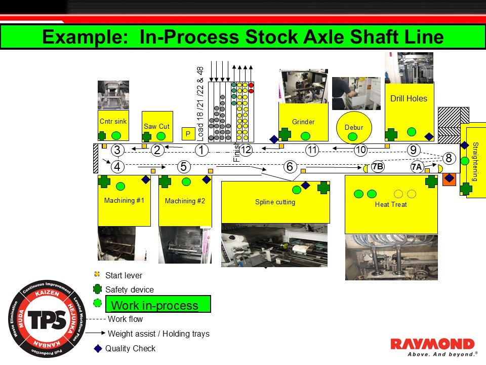
Figure 20: In-Process Stock Axle Shaft Line
Minimum in-process stock requirements across the axle shaft machining, drilling, spline cutting, and heat-treat processes.
In-process stock is one of the three required elements of Standardized Work. It defines the minimum quantity of parts needed between processes to maintain uninterrupted flow. This example, taken from an axle shaft machining and heat-treat line, shows how in-process stock stabilizes production when cycle times differ across processes.
The line includes center sink, saw cut, machining stages, grinding, deburr, drilling, spline cutting, heat treat, and straightening. Each process has unique characteristics and cycle times. Because they do not operate at the same pace, a minimum level of in-process stock is required to prevent downstream processes from starving or upstream processes from becoming blocked. In this example, eleven pieces of in-process stock are required to sustain continuous flow.
Green indicators on the diagram show the specific locations where these stock points exist. These points are not discretionary. They represent the minimum required amount of material needed for the line to remain stable. Increasing stock above the standard hides abnormalities and delays problem identification. Allowing stock to fall below the standard creates flow interruptions, leading to unevenness and overburden.
The flow arrows illustrate how material moves from process to process across the machining and heat-treat operations. Because certain processes, such as machining and heat treatment, have natural variation in timing, in-process stock functions as a stabilizing buffer. Without the defined minimum quantity, even small timing differences would cause frequent line interruptions.
Each process box includes icons indicating safety devices, quality checks, weight assist mechanisms, and manual work. These icons are part of Standardized Work because they define the required operating conditions. Leaders use these markers during confirmation to ensure that conditions remain stable throughout the shift.
This example shows how Standardized Work organizes complex process environments into a predictable system. When in-process stock standards are clear and maintained, the flow becomes stable and abnormalities become visible. When the standard is missing or not followed, waste, unevenness, and overburden quickly accumulate.
Instructor Notes
Reinforce that in-process stock represents the minimum required quantity, not a range.
Clarify that machining and heat-treat environments rely on tight control of buffering to prevent starving or blocking.
Highlight that excessive in-process stock hides real problems and delays improvement.
Emphasize that in-process stock is part of Standardized Work, not inventory.
Balanced Work Flow
Introduction
This section defines balanced work flow and explains why equal distribution of work elements between adjacent processes is necessary for stable flow and effective Standardized Work.
Figure 21: In-Process Stock – Axle Shaft Line
Shows minimum in-process stock locations required to stabilize flow across machining, drilling, spline cutting, and heat-treat processes.
Balanced work flow means that adjacent processes share work elements in a way that aligns with takt time. In TPS, balance is achieved when each process performs its required work content inside the takt interval so that material moves evenly through the line.
Balanced flow does not require that processes have identical work. It requires that each process performs the correct amount of work to meet takt time without overburden or waiting. When a process carries too much work, its cycle time exceeds takt time and creates delay. When a process carries too little work, idle time appears and improvement opportunities remain hidden.
Standardized Work supports balanced flow by defining the correct work sequence and timing at each process. By identifying each work element, leaders can confirm whether the work content fits inside takt time. When imbalances occur, tasks must be redistributed, reorganized, or improved so the line operates as one connected system.
Balanced work flow reduces unevenness, overburden, and waste. When work is balanced, in-process stock remains stable, interruptions decrease, and abnormalities become visible. Balanced work flow applies to assembly, machining, and mixed-model environments because all processes must align to takt time to maintain daily stability.
Instructor Notes
Balance must be measured relative to takt time.
Imbalance creates muda, mura, and muri.
Balancing requires ongoing confirmation and adjustment.
This concept connects directly to work sequence, work elements, and in-process stock.
Standardized Work Chart
Purpose of the Section
This section explains the purpose of the Standardized Work Chart, why it is displayed at the worksite, and how it supports visual control, supervision, and continuous improvement.
Figure 22: Standardized Work Chart
Shows the defined work method, operator motion, and sequence displayed at the worksite for visual control.
The Standardized Work Chart outlines the activity required to perform a process. It shows the operator’s movement, the work sequence, machine interaction, and the layout of tools and materials. Unlike the Standardized Work Combination Table, which focuses on timing, the Standardized Work Chart focuses on location and motion. It is displayed at the workstation so operators and leaders can see the correct method immediately.
The chart serves as a visual control. It defines the normal condition for the process. When operators follow the defined method, the work remains stable and predictable. When deviations occur, leaders can identify abnormalities quickly because the standard is visible. Without the chart, supervision would rely on memory and assumptions rather than a clear, displayed reference.
The Standardized Work Chart is also the baseline for kaizen. Because it shows how work is actually performed, leaders can evaluate whether layout changes, material presentation improvements, or motion reductions can strengthen the process. When improvements are confirmed, the chart must be updated so the improved method becomes the new standard. This prevents regression and ensures sustainability.
The chart reinforces leadership accountability. It shows that leaders are responsible for organizing the workplace, defining the correct motion, and maintaining the standard. A missing or outdated chart is a signal of weak process management. A clear, accurate chart is evidence of strong leadership and disciplined operations.
The Standardized Work Chart also supports operator training. By showing the correct motion and sequence visually, it allows new team members to learn the method consistently and reduces variation during training. This helps prevent incorrect or unsafe methods from becoming habits.
The chart is essential for a controlled production environment. It ensures that the method is clear, visible, and followed. It helps leaders find waste, unsafe steps, and improvement opportunities while protecting flow.
Instructor Notes
• Reinforce that visual control is a core TPS principle.
• Emphasize that the chart must always reflect the current method.
• Highlight that leaders own the responsibility of updating, confirming, and teaching the chart.
• Encourage participants to use the chart to identify motion waste, layout issues, and training needs.
Standardized Work Chart – Example Application
Introduction
This section explains how to read a real Standardized Work Chart and how it connects work elements, motion paths, machine interaction, and physical layout. It demonstrates how the chart functions as a visual control at the worksite and as the baseline for Standardized Work improvement.
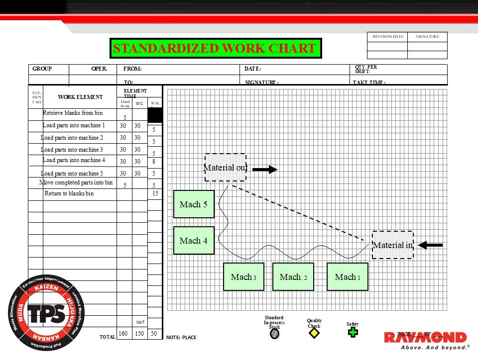
Figure 23: Standardized Work Chart – Example Application
Shows the operator path, machine layout, and work sequence used to confirm the correct method at the worksite.
The Standardized Work Chart documents the complete work sequence for the operator assigned to this machining process. It combines the three core elements of Standardized Work: work sequence, element time, and in-process stock. The chart is posted directly at the worksite so the correct method is visible to both operators and leaders.
On the left side, each work element is listed in order. Hand work time, machine time, and walking time are shown for each element. These times represent real observations on the line. Recording these times allows leaders to verify whether the operator can complete the full sequence within takt time and to identify steps that contain unnecessary motion or inefficiency.
The example shows the operator retrieving blanks, loading parts into five machines, removing completed parts, and returning to the blanks bin. Machine time is shown separately so leaders can see the relationship between operator motion and machine cycles. Walking time is identified where the operator travels between machines or material points. These details are essential for understanding motion waste and planning kaizen.
The right side of the chart shows the operator’s path in relation to the physical layout. Machines 1 through 5 are positioned according to the actual floor layout. The dashed line shows the walking path, including curved and diagonal movement. This visualization makes long travel routes visible, showing opportunities to rearrange equipment or relocate materials. Material in and material out positions are clearly marked, showing the start and end points of the operator’s cycle.
Symbols located below the chart indicate standard in-process stock, quality checks, and safety devices. These symbols communicate the required operating conditions for stability. Quality checks must occur at specific points. Safety devices such as interlocks or guards must be used consistently. These conditions are part of the standard and must be maintained.
The total times at the bottom of the element list show the total hand work, machine time, and walking time for one cycle. These totals allow leaders to confirm alignment with takt time. If total cycle time exceeds takt time, the work must be improved, reorganized, or redistributed.
The revision and signature fields indicate that leaders are responsible for maintaining the accuracy of the chart. When improvements are made, the Standardized Work Chart must be updated so the new method becomes the standard. This ensures discipline and prevents drift over time.
This example demonstrates the practical function of the Standardized Work Chart as a visual control and as the baseline for training, supervision, and kaizen. It clarifies the method, exposes waste, and protects flow.
Instructor Notes
Reinforce that every Standardized Work Chart must reflect the current best method.
Clarify that leaders use the chart to confirm work sequence, timing, layout, and in-process stock.
Emphasize that layout and motion kaizen depend on accurate path mapping.
Require that operators be trained directly from the chart to ensure consistent work methods.
Standardized Work Chart – Kaizen Improvement Example
Purpose of the Section
This section demonstrates how Standardized Work exposes motion waste and how layout changes can eliminate excessive walking, reduce cycle time, and strengthen flow. The example shows how a compact cell design generated a 19-second improvement.
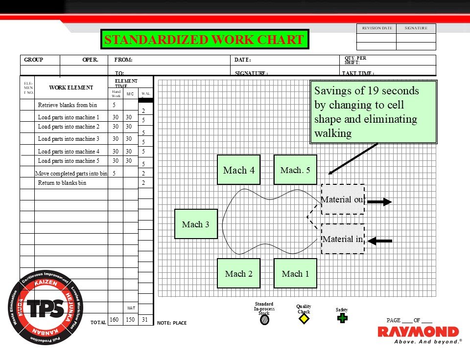
Figure 24: Standardized Work Chart – Kaizen Improvement Example
Shows how changing to a compact cell layout eliminated walking and reduced cycle time by 19 seconds.
This example shows how a Standardized Work Chart reveals motion waste and guides improvement. The original chart documented a long walking path between Machines 1 through 5. By mapping the operator’s motion, leaders could clearly see that the layout forced unnecessary travel between stations and between the material-in and material-out locations. The motion path loop was long, unbalanced, and introduced instability into the cycle.
After reviewing the chart, the team reconfigured the machines into a compact cell shape. This cell design reduced the distance between machines and created a smoother, continuous motion pattern. The updated layout eliminated the long walking loop entirely. As a result, a 19-second reduction in cycle time was achieved. This improvement is significant when measured against takt time and when repeated across hundreds of cycles each shift.
The revised Standardized Work Chart displays the new arrangement with Machines 1 through 5 positioned in a tight cluster. The operator’s walking pattern now follows a short and consistent route inside the cell. Material-in and material-out locations are adjacent to the work area, reducing handling time. The improved layout supports flow and reflects TPS principles such as motion economy, stability, and operator burden reduction.
The improvement also strengthens safety. By eliminating unnecessary walking, the operator faces fewer slip, trip, and collision risks. The shorter movement path reduces fatigue and prevents overburden. Stability improves because the operator can complete the work sequence within takt time with less variation and fewer opportunities for delay.
This kaizen demonstrates the core purpose of Standardized Work: making waste visible. When the work method is documented accurately, layout issues that are not obvious in daily production become clear in the motion diagram. Once the improvement is confirmed, the Standardized Work Chart must be updated so the new layout becomes the standard. This ensures that gains are held and future improvements build on a stable baseline.
This example reinforces that meaningful improvement does not require new equipment or complex systems. It requires clear visibility of the current method, disciplined observation, and the courage to reconfigure the workplace to support flow.
Instructor Notes
Reinforce that motion waste is often the largest hidden loss in many processes.
Emphasize that cell design reduces walking distance and stabilizes operator movement.
Clarify that improvements must be captured in both the Standardized Work Chart and the work sequence.
Encourage participants to look for long walking paths or motion loops when reviewing standardized work documentation.
Review
Introduction
This section reinforces the core concepts covered in the Standardized Work module. It confirms that participants can clearly explain takt time, cycle time, and the purpose of Standardized Work in their own words. These fundamentals must be understood before moving to advanced TPS applications.
Figure 25: Review Slide – Takt Time, Cycle Time, Standardized Work
Shows key review questions that confirm understanding of foundational Standardized Work concepts.
The review questions reinforce the fundamental concepts that form the base of all Standardized Work training. These concepts must be understood clearly before advancing to motion kaizen, line balancing, or Jidoka problem solving.
Takt time is the required pace of production needed to meet customer demand. It is calculated by dividing available operating time by required units. Takt time defines the rhythm the line must follow.
Cycle time is the actual time required for an operator or process to complete all elements of the work and return to the starting point. It is confirmed through direct observation at the workstation and includes hand work, walking, waiting, and machine time.
Understanding the relationship between takt time and cycle time is essential. Takt time reflects customer demand. Cycle time reflects process capability. Comparing the two reveals whether the process is stable, overloaded, or underloaded.
The purpose of Standardized Work is to define the best known method, create stability, identify abnormalities, and provide a baseline for kaizen. By documenting the correct sequence, timing, and layout, Standardized Work supports consistent training, predictable output, and structured improvement activity.
These review questions confirm that participants understand the foundational logic behind TPS work design and can articulate these principles before applying them on the shop floor.
Instructor Notes
Confirm participants can explain takt time without referring to notes.
Reinforce that cycle time must be directly observed at the gemba.
Emphasize that Standardized Work is both the baseline and the launch point for improvement.
Use this section to transition into hands-on confirmation or shop floor exercises.
Thank You / Copyright Notice
Purpose of the Section
This section closes the Standardized Work module with a formal thank-you message and a clear copyright statement. It reinforces that all LeanTPS Basic Training materials are proprietary and protected.
Figure 25: Thank You and Copyright Notice
Formal closing message with LeanTPS trademark™ and copyright© protection.
This closing slide concludes the Standardized Work module for LeanTPS Basic Training. It provides a formal thank-you message in English, Japanese, and Romanized Japanese, reflecting the Toyota roots of the training content and the respect shown to participants who commit to learning TPS correctly.
The thank-you message reinforces the learning relationship. LeanTPS Basic Training is designed to help participants build thinking capability, understand the purpose of Standardized Work, and apply TPS principles to develop stable work methods. The closing slide acknowledges the effort required to learn these principles and encourages continued study and application in daily work.
The copyright notice clarifies that all training visuals, structures, work examples, and explanations are protected intellectual property belonging to David Devoe and LeanTPS. These materials originate from years of Toyota training, field application, and development of LeanTPS methods. Because the materials include original diagrams, layouts, Standardized Work examples, and TPS-based logic, they require formal protection to ensure they are used responsibly and not misrepresented or commercialized without authorization.
The copyright statement outlines the permitted use: personal development and review within the LeanTPS Basic Training Program. It restricts reproduction, distribution, resale, translation, or adaptation without written permission. This ensures the integrity of the system and protects the accuracy of TPS knowledge in public use.
The trademarks LeanTPS™, Lean TPS Basic Training™, and Lean TPS Swiss Cheese Model™ are formally noted to reinforce brand identity and intellectual ownership. This protects the structure and terminology used in the training system and supports consistent communication across all LeanTPS materials.
This final section closes the training module with respect, clarity, and the formal protections required to preserve the integrity of the LeanTPS system.
Instructor Notes
Reinforce that all LeanTPS training materials are protected and cannot be reused without permission.
Encourage participants to continue learning through application, not theory.
Confirm understanding of takt time, cycle time, and the purpose of Standardized Work before moving to the next module.
Use this slide to formally close the session and transition to discussion or Q&A.
Closing Statement
Mohamed, this module has been prepared for your study as the baseline for understanding Standardized Work inside Toyota operations. It contains the complete structure, terminology, examples, and visual logic required to see how takt time, sequence, and in-process stock connect to stability and flow. Review this material carefully before we continue to the next section of your training, as all future TPS methods build directly on the foundations established here.